
Photovoltaic power generation system maximum power point tracing system and method

A photovoltaic power generation system and maximum power point technology, which is applied in photovoltaic power generation, control/regulation systems, and electrical variable adjustment, can solve the problem that the maximum power point tracking does not achieve the optimal effect, it is difficult to track the maximum power point, and the amount of calculation is large And other issues

Inactive Publication Date: 2013-05-15
CHONGQING UNIV
View PDF7 Cites 26 Cited by
  • Summary
  • Abstract
  • Description
  • Claims
  • Application Information

AI Technical Summary

Problems solved by technology

Such as fuzzy neural network reasoning system, genetic algorithm, radial function neural network algorithm, but the model adjustment time of these methods is long and the calculation amount is large
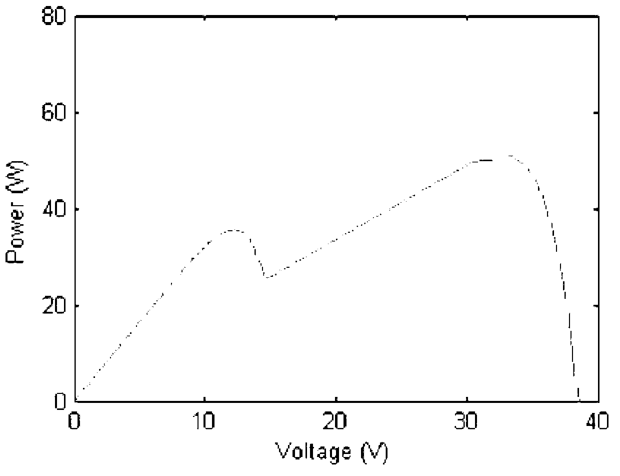
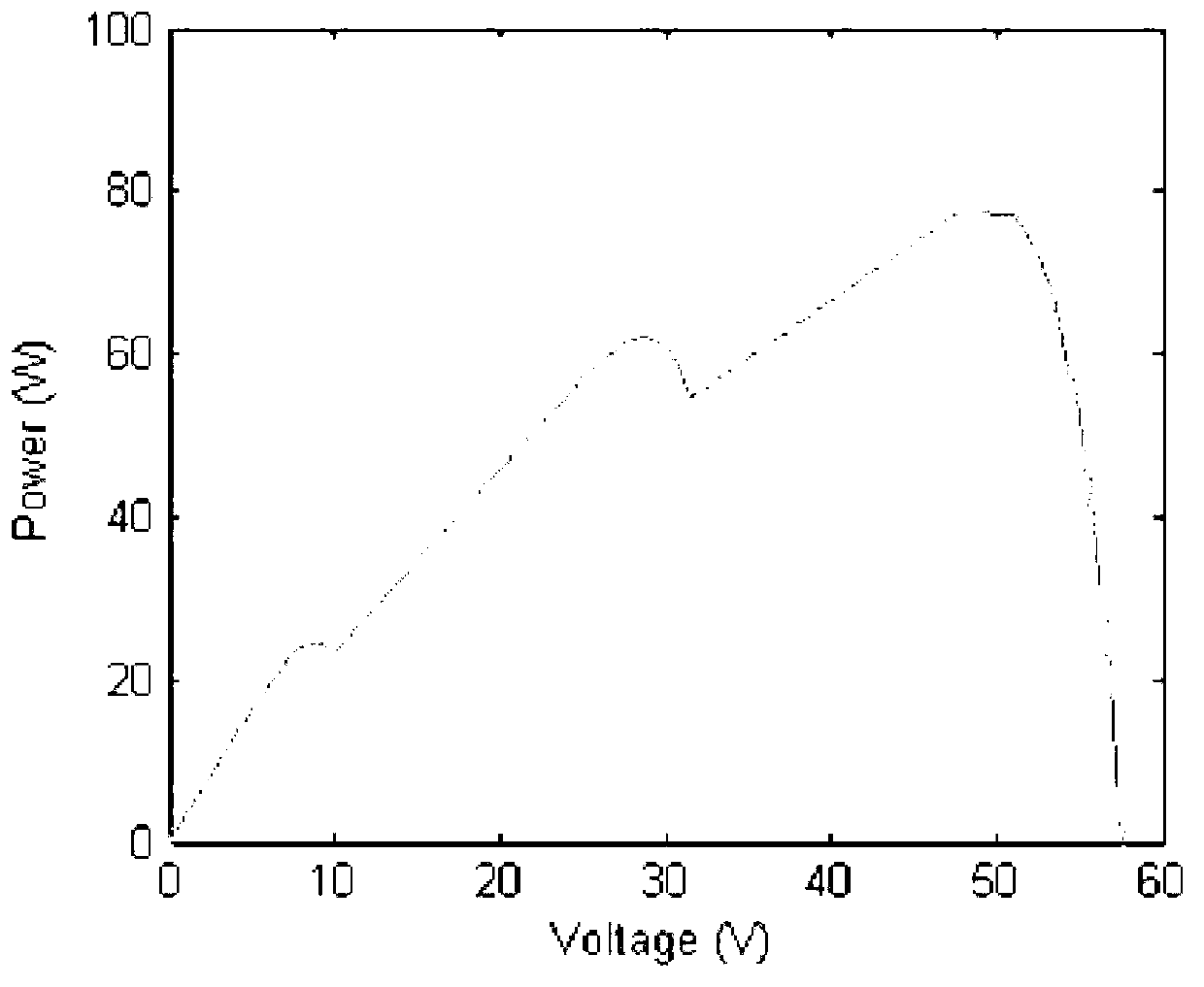
[0005] At the same time, due to the existence of multiple peak power points in photovoltaic cells under uneven illumination conditions, it becomes more difficult to quickly and accurately track the global maximum power point.
In the past 5 years, people have also done a lot of research on the tracking control strategy of the maximum power point of the photovoltaic array under the condition of uneven illumination, and proposed methods such as intelligent search method, Fibonacci sequence, peak point search, etc., but None of these methods achieve optimal results in maximum power point tracking under shading conditions.

Method used


Image

  • Photovoltaic power generation system maximum power point tracing system and method
  • Photovoltaic power generation system maximum power point tracing system and method
  • Photovoltaic power generation system maximum power point tracing system and method

Examples


Embodiment Construction

[0044] Embodiments of the present invention are described in detail below, examples of which are shown in the drawings, wherein the same or similar reference numerals designate the same or similar elements or elements having the same or similar functions throughout. The embodiments described below by referring to the figures are exemplary only for explaining the present invention and should not be construed as limiting the present invention.

[0045] In the description of the present invention, unless otherwise specified and limited, it should be noted that the terms "installation", "connection" and "connection" should be understood in a broad sense, for example, it can be mechanical connection or electrical connection, or two The internal communication of each element may be directly connected or indirectly connected through an intermediary. Those skilled in the art can understand the specific meanings of the above terms according to specific situations.

[0046] Such as im...


PUM


Abstract

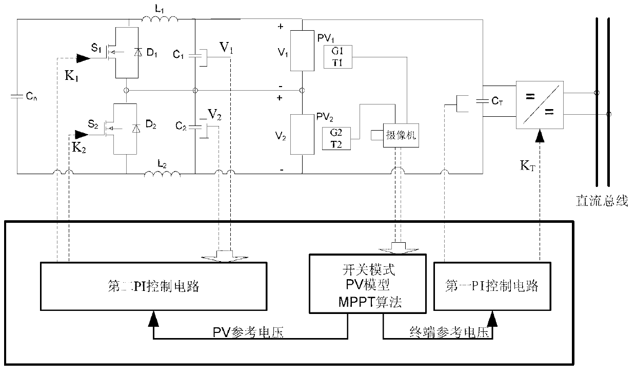
The invention provides a photovoltaic power generation system maximum power point tracing system and a method and belongs to the technical field of photovoltaic power generation. The photovoltaic power generation system maximum power point tracing system uses monitoring devices of a photovoltaic power generation site to obtain video image information in real time and uses an image processing technology to confirm parameters such as the location, size of a shadow area, and temperature and illumination of a shielded portion of a photovoltaic cell. The method includes: building a photovoltaic cell mould under uneven lighting, using the parameters as input parameters of expansion memory particle swarm optimization, caculating ideal working voltage of each battery cell and the whole photovoltaic power generation system, finally using differential value of the ideal working voltage and the actual output voltage as input of a two-way C`uk converter and a terminal Boost converter control circuit, generating pulse width modulation (PWM) signals, enabling the maximum power point and output of the whole system during working of each photovoltaic cell to the most, and ensuring the shielded photovoltaic cells not to be load and consume system energy until being burnt.

Description

technical field [0001] The invention relates to a maximum power point tracking system and method for a photovoltaic power generation system, in particular to a maximum power point tracking method for a photovoltaic power generation system that is based on an extended memory particle swarm method and can realize uneven illumination conditions. Background technique [0002] Under the condition of uniform illumination and constant temperature, the output characteristic curve (I-V curve and P-V curve) of the photovoltaic power generation system is a nonlinear single-peak curve with a unique peak point. Using the traditional maximum power point tracking algorithm, the photovoltaic The power generation system works at the maximum power point. [0003] However, in fact, due to the wide distribution of photovoltaic panels in the photovoltaic power generation system, the temperature and light intensity distribution of each photovoltaic panel is uneven, such as: a large photovoltaic p...

Claims


Application Information

Patent Timeline
Patent Type & Authority Applications(China)
IPC IPC(8): G05F1/67
CPCY02E10/58Y02B10/14Y02B10/10Y02E10/56
Inventor 段其昌徐宏英段盼杨帆胡博
Owner CHONGQING UNIV
Learn More