Power supply wire for high-frequency current

A high-frequency current and wire technology, used in circuits, power cables with shielding/conducting layers, insulated cables, etc., can solve problems such as fire, and achieve suppression of AC resistance increase, prevention of disconnection, and partial resistance. The effect of a rise in value

Active Publication Date: 2013-05-15
KANZACC
View PDF16 Cites 4 Cited by
  • Summary
  • Abstract
  • Description
  • Claims
  • Application Information

AI Technical Summary

Problems solved by technology

This rise in resistance value may also be the cause of fire

Method used


Image

  • Power supply wire for high-frequency current
  • Power supply wire for high-frequency current
  • Power supply wire for high-frequency current

Examples


Embodiment Construction

[0026] Hereinafter, the high-frequency current supply electric wire of this invention is demonstrated based on drawing.

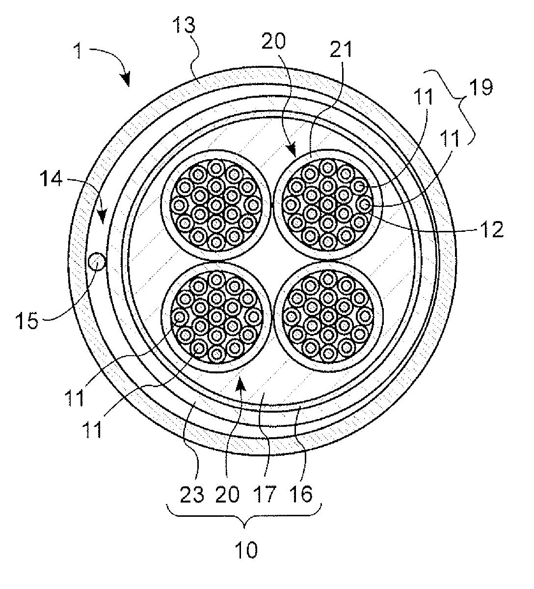
[0027] Such as figure 1 As shown, the high-frequency current supply electric wire 1 of the present invention is composed of a corrugated tube 13 and a composite electric wire 10 disposed inside the corrugated tube 13 .

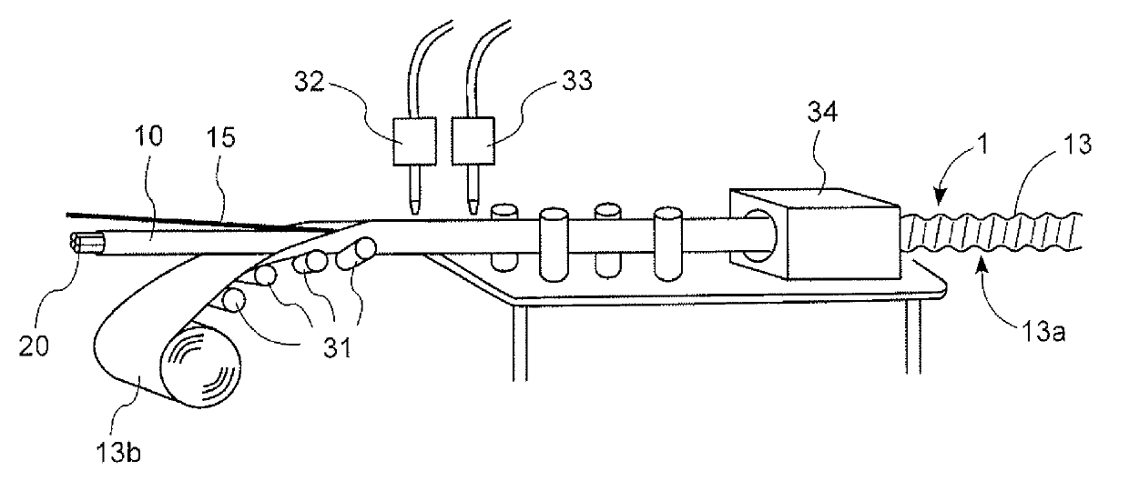
[0028] The corrugated tube 13 is a member that surrounds and protects the composite electric wire 10, and the corrugated tube 13 is a tube made of metal such as aluminum, aluminum alloy, copper, copper alloy, stainless steel, or steel. A corrugated bent portion 13a ( figure 2 ), and the bent portion 13a is helically formed around the tube. In order to prevent corrosion of the bellows 13 , an anticorrosion layer made of resin, coal tar, or the like may be formed on the outer peripheral surface of the bellows 13 . Here, the dimensions of the bellows 13 of the present invention are, for example, a plate thickness of 0.3 mm and an outer dia...


PUM

PropertyMeasurementUnit
diameteraaaaaaaaaa
diameteraaaaaaaaaa

Abstract

The invention provides a power supply wire for high-frequency current which reduces a supply loss of current affected by the skin effect and has a high degree of freedom in laying. The power supply wire for high-frequency current (1) comprises: a corrugated tube made of metal (13); a combined electric wire (10) disposed inside the corrugated tube (13) and including a plurality of unit electric wires (20) and a sheath material (23), each of the unit electric wires (20) being formed by bundling together a plurality of conductive wires (11) individually coated with insulating films (12), and the sheath material (23) covering the plurality of unit electric wires (20); and a gap (14) formed between the corrugated tube (13) and the combined electric wire (10).

Description

technical field [0001] The present invention relates to an electric wire for supplying high-frequency current. Background technique [0002] An electric wire described in Patent Document 1 has been proposed as a shielded electric wire. This electric wire has an effect of blocking electromagnetic waves from the core wire by surrounding the outer peripheral surface of the core wire with a conductive corrugated tube. In addition, since this electric wire can prevent damage to the core wire received from the outside, it can be used as a power supply electric wire. [0003] However, when this electric wire is used as a high-frequency current supply electric wire in the frequency range of 30kHz to 100kHz, since the current density flowing in the core wire decreases due to the skin effect, it is not possible to efficiently supply electric power . In addition, since the inside of the corrugated tube is filled with the resin layer, the pressing force generated by the bending of th...

Claims


Application Information

Patent Timeline
Patent Type & Authority Applications(China)
IPC IPC(8): H01B7/17H01B7/20H01B7/00
CPCH01B7/16H01B7/1895H01B9/02H01B7/303
Inventor 平池弘司小西进次郎
Owner KANZACC
Why Eureka
Try Eureka