Switch converter two-edge pulse frequency modulation C-type control method and device thereof

A pulse frequency modulation and switching converter technology, applied in the direction of output power conversion devices, electrical components, etc., can solve the problems of sub-harmonic oscillation and affecting the stability of the converter, and achieve good transient performance and system stability. , the effect of high voltage regulation accuracy

Active Publication Date: 2015-07-08
SOUTHWEST JIAOTONG UNIV
View PDF3 Cites 0 Cited by
  • Summary
  • Abstract
  • Description
  • Claims
  • Application Information

AI Technical Summary

Problems solved by technology

However, the traditional current-mode control method (peak current control) will generate sub-harmonic oscillation when the duty cycle is greater than 0.5, which seriously affects the stability of the converter.

Method used


Image

  • Switch converter two-edge pulse frequency modulation C-type control method and device thereof
  • Switch converter two-edge pulse frequency modulation C-type control method and device thereof
  • Switch converter two-edge pulse frequency modulation C-type control method and device thereof

Examples


Embodiment 1

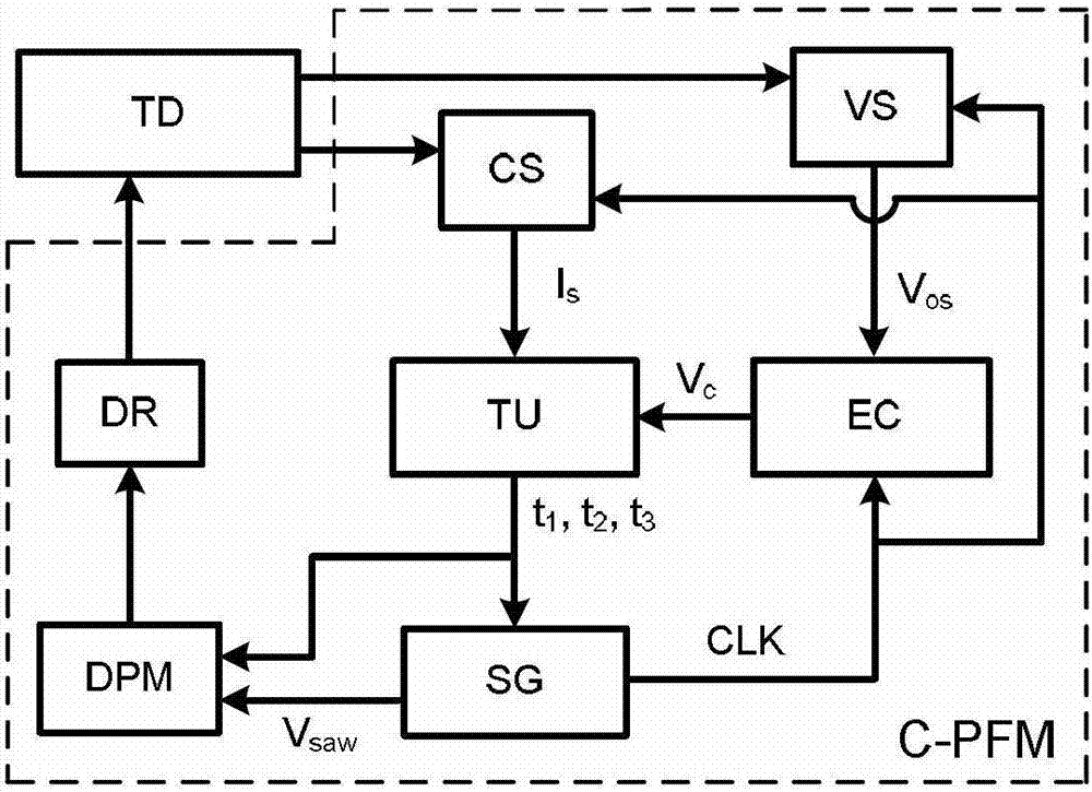
[0033] figure 1 It is shown that a specific embodiment of the present invention is: a switching converter double-edge pulse frequency modulation C-type control method and its device C-PFM, and its C-PFM device is mainly composed of a voltage detection circuit VS, a current detection circuit CS, an error Compensator EC, time operation unit TU, variable frequency sawtooth wave generator SG, double edge pulse modulator DPM and drive circuit DR. The voltage detection circuit VS is used to obtain the output voltage value V os , the current detection circuit CS is used to obtain the inductor current value I s , the error compensator EC is used to generate the control voltage V c , the time operation unit TU is used to generate three periods of time t 1 , t 2 , t 3 , the variable frequency sawtooth wave generator SG is used to generate variable frequency sawtooth wave V saw and the sampling pulse signal CLK, the double-edge pulse modulator DPM is used to generate t 1 , t 2 , ...

Embodiment 2

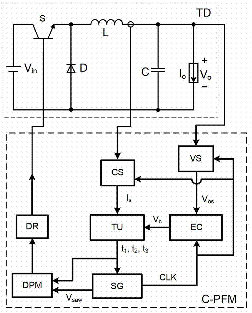
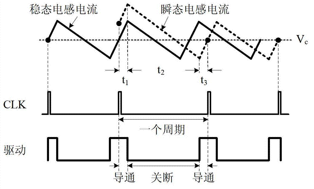
[0043] Figure 8 It is shown that the converter TD controlled in this example is a Boost converter, and the control device of the switching tube S adopts C-PFM. Figure 9 In Example 2 of the present invention, the inductor current, the control voltage V c , time t 1 , time t 2 , time t 3 , a schematic diagram of the relationship between the sampling pulse signal CLK and the driving signal.

[0044] The specific working process and principle are: Figure 8 , Figure 9 It shows that the switching tube is turned off at any starting moment of the sampling pulse signal CLK, and at the same time, the voltage detection circuit VS detects the output voltage of the converter TD to obtain the output voltage value V os , the current detection circuit CS detects the inductor current of the converter TD, and obtains the inductor current value I s , the output voltage value V os with reference voltage V ref Send them together to the error compensator EC to generate the control volt...

Embodiment 3

[0047] Such as Figure 10 As shown, this example is basically the same as the first example, except that the converter TD controlled in this example is a Buck-Boost converter.

[0048] The inventive method can also be used for Cuk converter, SEPIC converter, Zeta converter, forward converter, flyback converter, push-pull converter, half-bridge converter except being applicable to the switching converter in the above embodiment. , full-bridge converter and other circuit topologies.


PUM


Abstract

The invention discloses a switch converter two-edge pulse frequency modulation C-type control method and a device thereof. The method comprises the following steps: according to the relationship of control voltage Vc and inductive current Is which are generated by reference voltage reference (VREF) and output voltage Vos through an error compensator, combining preset constant-on-time and constant-off-time to generate three periods of time t1, t2 and t3, and sequentially adopting control timing sequences composed of t1, t2 and t3 in each period to control on-off of a switch tube of a switch converter. The switch converter two-edge pulse frequency modulation C-type control method and the device thereof can be used for a plurality of topological-structure switch converters such as a buck converter, a booster converter, a buck-boost converter, a cuk converter, a single-ended primary industry converter (SEPIC), and a zero energy thermonuclear assembly (ZETA) converter. The switch converter two-edge pulse frequency modulation C-type control method and the device thereof have the advantages of being fast in transient response speed, high in voltage stabilization precision, good in stability performance, small in electromagnetic noise, strong in capacity of resisting disturbance, and wide in application range, and having the current-limiting function.

Description

technical field [0001] The invention relates to power electronic equipment, in particular to a control method and device for a switching converter. Background technique [0002] With the continuous development of power electronic devices and the continuous updating of power electronic converter technology, switching power supply technology, as an important field of power electronics, has received more and more attention and research. The switching power supply is mainly composed of two parts: a switching converter and a control circuit. The switching converter is also called the power main circuit, and mainly has various topologies such as buck, boost, buck-boost, forward, flyback, half-bridge, and full-bridge. The control circuit is used to monitor the working state of the switching converter, and generate a control pulse signal to control the switching tube of the switching converter, and adjust the energy supplied to the load to stabilize the output. For the same switch...

Claims


Application Information

Patent Timeline
Patent Type & Authority Patents(China)
IPC IPC(8): H02M1/08
Inventor 周国华金艳艳吴松荣许建平
Owner SOUTHWEST JIAOTONG UNIV
Why Eureka
Try Eureka