
Dynamic linear control light emitting diode (LED) driver circuit

A technology of LED drive and linear control, applied in the direction of lamp circuit layout, electric light source, lighting device, etc., can solve the problem of low efficiency and achieve the effect of improving efficiency and increasing efficiency

Active Publication Date: 2013-05-15
上海芯飞半导体技术有限公司
View PDF3 Cites 32 Cited by
  • Summary
  • Abstract
  • Description
  • Claims
  • Application Information

AI Technical Summary

Problems solved by technology

[0008] The technical problem to be solved by the present invention is to provide a dynamic linear control LED drive circuit for the defect of low efficiency of the linear control LED drive circuit in the prior art

Method used


Image

  • Dynamic linear control light emitting diode (LED) driver circuit
  • Dynamic linear control light emitting diode (LED) driver circuit
  • Dynamic linear control light emitting diode (LED) driver circuit

Examples


Embodiment Construction

[0036] In order to make the object, technical solution and advantages of the present invention clearer, the present invention will be further described in detail below in conjunction with the accompanying drawings and embodiments. It should be understood that the specific embodiments described here are only used to explain the present invention, not to limit the present invention.

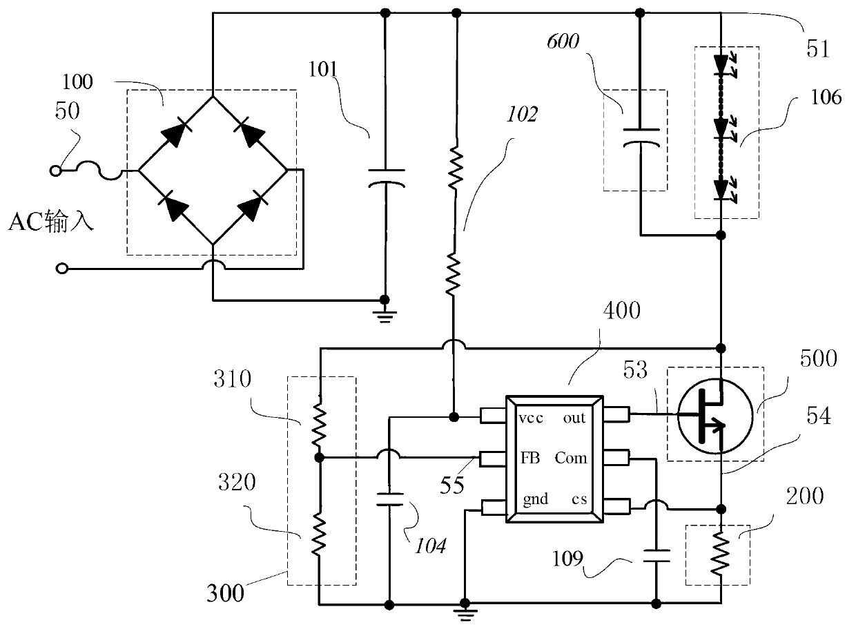
[0037] image 3 It shows a schematic circuit diagram of a dynamic linear control LED driving circuit according to an embodiment of the present invention, as shown in image 3As shown, the dynamic linear control LED drive circuit (hereinafter referred to as the drive circuit for short) includes: a rectification module 100 , a sampling module 200 , a feedback module 300 , a constant current control module 400 and a constant current drive module 500 . Wherein, the rectification module 100 can convert the input commercial power signal into a linear driving voltage signal, and output the linear driving...


PUM


Abstract

The invention discloses a dynamic linear control light emitting diode (LED) driver circuit which comprises a rectifier module, a sampling module, a feedback module, a constant-current control module, a constant-current driver module. The rectifier module is used for converting input mains supply signals to linear driving voltage signals which are output to an LED load. The sampling module is used for acquiring driving current which flows through the LED load. The feedback module is used for acquiring the linear driving voltage signals. The constant-current control module is used for generating constant current adjusting signals according to the driving current and generating constant current control signals according to the linear driving voltage signals. The constant-current driver module is used for controlling current of the load to be constant current according to the constant current adjusting signals and the constant current control signals. According to the dynamic linear control LED driver circuit, a conducting mode and a non-conducting mode of a power switch can be chosen according to the magnitude of linear voltage of the LED load, and therefore the linear LED driving efficiency can be greatly improved. More specially, when input voltage is low and the LED load is in a high-working-efficiency mode, the constant-current control module enables the power switch to be in the conducting mode, and therefore a constant current output state of an LED is guaranteed; and when the input voltage is high and the LED load is in a low-working-efficiency mode, the constant-current control module enables the power switch to be shut down forcibly.

Description

technical field [0001] The invention relates to LED driving, in particular to a dynamic linear control LED driving circuit. Background technique [0002] With the popularization of green lighting, light-emitting diode (LED: Light Emitting Diode) lighting has been developed rapidly. LED driving power is generally realized by switching power supply. Linear drive power is abandoned by engineers because of efficiency issues. figure 1 is a schematic diagram of a traditional LED linear drive circuit, such as figure 1 As shown, the rectifier bridge 110 is composed of four high-voltage diodes, and the filter capacitor 101 rectifies the mains signal (usually a sinusoidal AC voltage) into a DC voltage. The power supply module of the control chip 105 includes a voltage dividing resistor 102, a clamping diode 103, and a decoupling capacitor 104 of the control chip. The power supply module can divide a voltage of about 10V from an input voltage of about 300VDC to work for the driver c...

Claims


Application Information

Patent Timeline
IPC IPC(8): H05B37/02
Inventor 廖伟明郑曰胡小波
Owner 上海芯飞半导体技术有限公司
Features
  • Generate Ideas
  • Intellectual Property
  • Life Sciences
  • Materials
  • Tech Scout
  • Unparalleled Data Quality
  • Higher Quality Content
  • 60% Fewer Hallucinations
Learn More