Optical calibration method of ultrasonic probe

A calibration method, ultrasonic technology, applied in the field of optical calibration, can solve problems such as low adaptability, complex equipment, and restricted activities, and achieve the effects of clear physical meaning, reduced complexity, and wide application range

Inactive Publication Date: 2013-05-22
DALIAN UNIV OF TECH
View PDF4 Cites 34 Cited by
  • Summary
  • Abstract
  • Description
  • Claims
  • Application Information

AI Technical Summary

Problems solved by technology

[0004] (1) The designed N-shaped calibration template is only a two-dimensional calibration template in space, and the obtained calibration template coordinates lack the third-dimensional spatial information;
[0005] (2) Calibration formula P(C)= C T T * T T R * R T I *The unknowns in P(I) are C T T and R T I Two, the calculation is more complicated, and multiple calibration images need to be collected;
[0006] (3) By default, the receiver coordinate system is used instead of the ultrasonic probe coordinate system, and there may be transformation errors;
[0007] (4) It is necessary to fix the electromagnetic receiver on the ultrasonic probe, the movement is limited, and different specifications of electromagnetic positioners need to be equipped for different types of ultrasonic probes, which makes the equipment complicated and the adaptability is not high;
[0008] (5) Electromagnetic positioning equipment has electromagnetic compatibility problems in surgical navigation applications

Method used


Image

  • Optical calibration method of ultrasonic probe
  • Optical calibration method of ultrasonic probe
  • Optical calibration method of ultrasonic probe

Examples


Embodiment 1

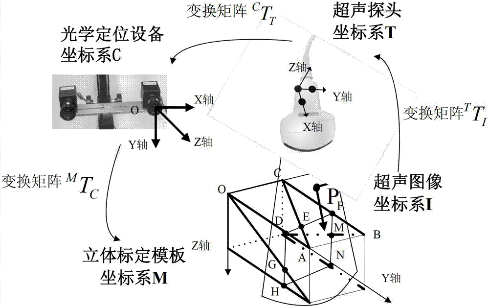
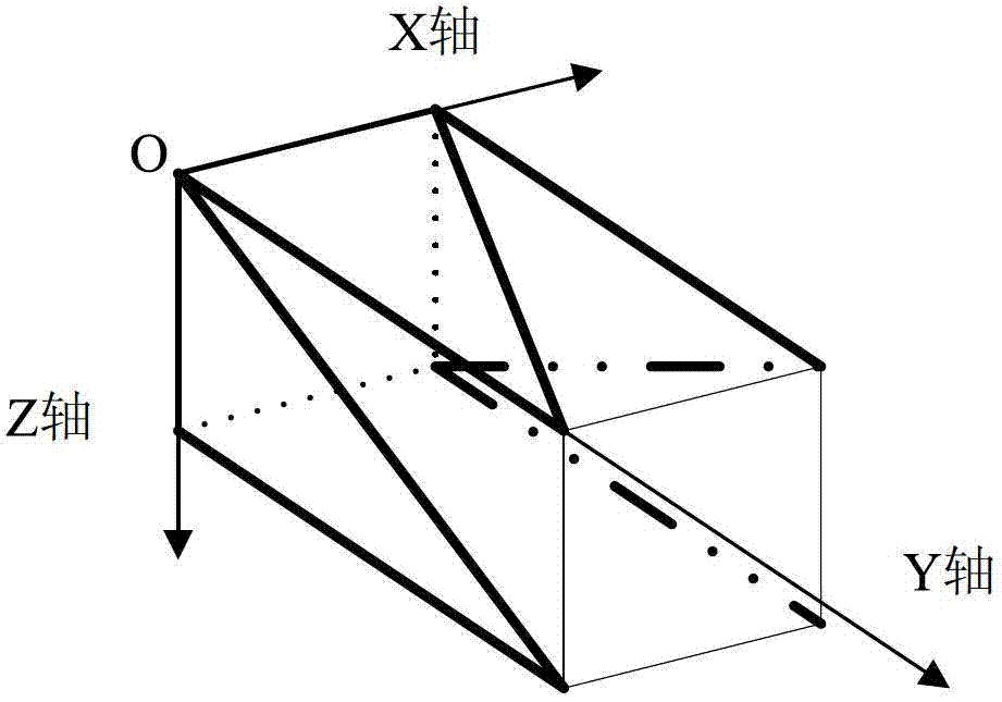
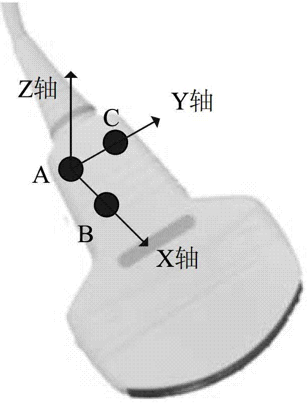
[0038] Such as Figure 1-5 Shown: a calibration method of ultrasonic probe:

[0039] one. Setting of the coordinate system C of the optical positioning device: select two identical cameras whose optical axes are parallel to each other as the optical positioning device. Such as figure 1 As shown, two identical cameras are equipped with the same type of lens, and preferably, they are fixed on a fixed frame arranged horizontally.

[0040] Further, in order to meet different calibration ranges, the two cameras are movably connected to the fixed frame, that is, the distance between the optical centers of the two cameras, that is, the baseline distance, is set to be adjustable, and the optical axes of the two cameras are clamped The angle can also be adjusted to meet the calibration needs of different orientations.

[0041] After fixing the optical instrument, usually, choose the optical center of the left camera as the axis, the baseline of the two cameras as the X axis, and th...


PUM


Abstract

The invention discloses an optical calibration method of an ultrasonic probe. The optical calibration method of the ultrasonic probe includes the following steps: (1) pasting character identification points on the ultrasonic probe, (2) fixing a three-dimensional calibration template and optical positioning equipment, (3) and holding the ultrasonic probe in hand to scan the three-dimensional calibration template, obtaining a space gesture of the ultrasonic probe by using the optical positioning equipment at the time of every time gathering ultrasound images to obtain original data and calibrating the ultrasonic probe by using a least square method. Compared with a traditional electromagnetic calibration method, the optical calibration method of the ultrasonic probe has the advantages that calibration results are more accurate, due to the fact that in the process of calculation only an unknown number exists (an unknown transformation matrix), complexity of calibration calculation is reduced, the optical calibration method of the ultrasonic probe can be applied into various types of ultrasound probes, equipment is simple and convenient and range of application is wide. The optical positioning equipment is used for obtaining the gesture of the ultrasonic probe, influence of power cords is not needed to consider and calibration range is wider, and the optical positioning equipment does not have a problem of electromagnetic compatibility in a surgical navigation environment.

Description

technical field [0001] The invention relates to an optical calibration method, in particular to an optical calibration method of an ultrasonic probe. Background technique [0002] Existing manual three-dimensional ultrasonic image calibration method based on the magnetic locator: fix an electromagnetic receiver on the ultrasonic probe, utilize the electromagnetic locator to obtain the spatial information of the receiver relative to the transmitter, and establish the ultrasonic image coordinate system I, receiver Coordinate system R, emitter coordinate system T, template coordinate system C four coordinate systems, the calibration formula is P(C)= C T T · T T R · R T I · P(I), where T T R Represents the transformation matrix from the electromagnetic receiver to the transmitter, the ultrasonic image coordinates P(I) of known spatial points, the corresponding template coordinates P(C) and the measured T T R , using the least squares method to obtain the spatial mapping...

Claims


Application Information

Patent Timeline
Patent Type & Authority Applications(China)
IPC IPC(8): A61B8/00
Inventor 邱天爽任亮朱勇刘惠
Owner DALIAN UNIV OF TECH
Why Eureka
Try Eureka