Metal plastic forming device with bidirectional extrusion function

A plastic forming and bidirectional extrusion technology, applied in the field of metal plastic forming devices, can solve the problems of excessive wear of hydraulic cylinder seals, increase in cost, increase in die loss, etc., achieve reliable operation, reduce energy supply requirements, and maintain handy effect

Inactive Publication Date: 2013-05-22
龙西新 +2
View PDF7 Cites 7 Cited by
  • Summary
  • Abstract
  • Description
  • Claims
  • Application Information

AI Technical Summary

Problems solved by technology

However, the metal filling in the single-direction extrusion processing of a single power head is not ideal. In order to obtain the required shape, the deformation of the billet is usually very large, resulting in increased die loss and increased pressure exerted by the power head.
However, for multi-power heads and multi-directional extrusion devices, one more working oil cylinder will increase the cost of the machine tool for each power head, and the direction of the reaction force of the metal flow on the power head is very complicated when multiple power heads work at the same time, which will easily cause the power head to be affected. The partial load causes the hydraulic cylinder seal to wear too quickly or the power head breaks
As mentioned in Patent No. 201010513506.4, the patent adopts multi-power heads and multi-directional extrusion methods. When the main body of the machine tool is huge and multi-cylinders work together, there may be unbalanced loads on the punches. Increased wear

Method used


Image

  • Metal plastic forming device with bidirectional extrusion function

Examples


Embodiment Construction

[0023] The present invention will be further described below in conjunction with drawings and embodiments.

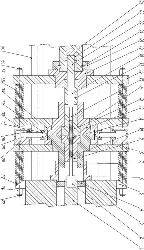
[0024] refer to figure 1 , this embodiment includes a master cylinder piston rod 24, an intermediate moving plate 14, an upper punch 15, a dowel 22, an upper die core 13, an upper stress ring 12, Lower stress circle 7, lower mold core 9, lower moving plate 8, lock 34, lock piston rod 29, lower girder 3, buckle barrel 6, lower punch 2, upper moving plate 16, first limit spring 27, The first limit rod 25, the second limit spring 38, the second limit rod 35;

[0025] The master cylinder piston rod 24 is fixedly connected with the upper mold base 19 through the key 21 and the key cap 20, the upper mold base 19 is connected with the upper moving plate 16 by bolts, and the upper punch 15 is connected with the upper punch base. 18 is connected by threads, and the upper punch guide sleeve 17 is arranged outside the upper punch seat 18, and the upper punch seat 18 is tightly p...


PUM


Abstract

The invention discloses a metal plastic forming device with a bidirectional extrusion function. The metal plastic forming device comprises a main cylinder piston rod in a main operating cylinder, a middle movable plate, an upper punch, a force transfer rod, an upper die core, an upper stress ring, a lower stress ring, a lower die core, a lower movable plate, a lock catch, a lock catch piston rod, a lower crossbeam, a fastening cylinder, a lower punch, an upper movable plate, a first limiting spring, a first limiting rod, a second limiting spring and a second limiting rod. According to the device, only a main operating cylinder and a main cylinder piston rod which corresponds to the main operating cylinder need to serve as power heads, and then blanks can be extruded in up and down directions, so that a machine tool is simple in structure, and the manufacturing cost is greatly reduced; due to bidirectional extrusion, the deformation coefficient of materials is lowered, the possibility of internal cracks of parts is low, and the requirements on energy supply are reduced; and moreover, the device is reliable in operation and convenient to maintain.

Description

technical field [0001] The invention relates to a metal plastic forming extrusion device, in particular to a metal plastic forming device with bidirectional extrusion function. Background technique [0002] Metal plastic forming extrusion technology is to put the pretreated metal blank into the mold according to the principle of metal plastic deformation, and then apply pressure on the blank to deform the blank metal and fill the mold cavity to obtain the required parts. [0003] At present, general metal plastic forming equipment adopts one-way extrusion with single power head or multi-directional extrusion with multiple power heads, among which one-way extrusion with single power head is the most common. However, the metal filling of single-power head unidirectional extrusion is not ideal. In order to obtain the desired shape, the deformation of the billet is usually very large, which leads to increased die loss and increased pressure on the power head. However, for multi...

Claims


Application Information

Patent Timeline
Patent Type & Authority Applications(China)
IPC IPC(8): B21C23/21
Inventor 龙西新杨靖文仲敏
Owner 龙西新
Why Eureka
Try Eureka