Testing device and method for resonant mode optical gyroscope scale factor

A technology of scale factor and optical gyroscope, which is applied in the field of optical gyroscope, can solve the problems of gyroscope test result influence and tedious test process, etc., and achieve the effect of improving test efficiency, convenient operation and test accuracy

Active Publication Date: 2013-05-22
BEIHANG UNIV
View PDF6 Cites 19 Cited by
  • Summary
  • Abstract
  • Description
  • Claims
  • Application Information

AI Technical Summary

Problems solved by technology

This test method requires a gyro fixing fixture and a turntable, the test process is relatively cumbersome, and the vibrat...

Method used


Image

  • Testing device and method for resonant mode optical gyroscope scale factor
  • Testing device and method for resonant mode optical gyroscope scale factor
  • Testing device and method for resonant mode optical gyroscope scale factor

Examples


Embodiment Construction

[0043] The present invention will be further described in detail below in conjunction with the accompanying drawings.

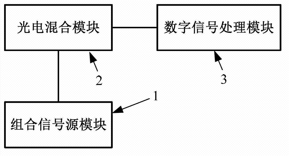
[0044] The present invention proposes a resonant optical gyroscope scale factor testing device, such as figure 1 As shown, it includes a combined signal source module 1, a photoelectric hybrid module 2 and a digital signal processing module 3;

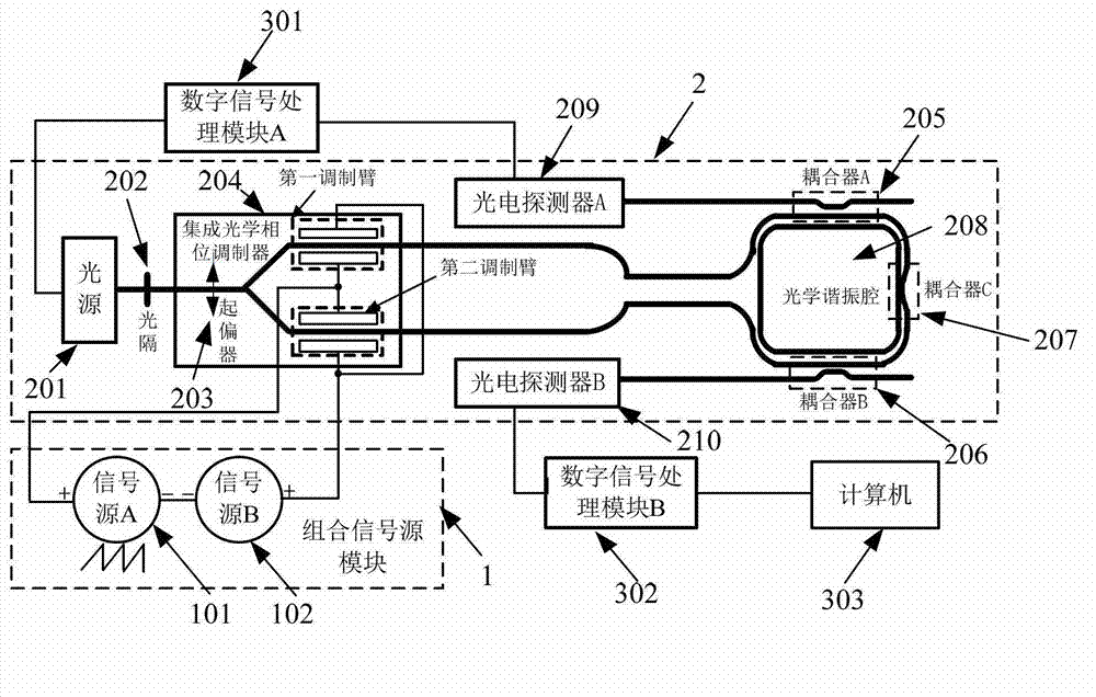
[0045] Such as figure 2 As shown, the combined signal source module 1 includes a signal source A101 and a signal source B102;

[0046] Signal source A101 generates a sawtooth wave signal, signal source B102 generates a modulation signal, signal source A101 and signal source B102 are connected in series, the negative electrodes of the two signal sources are connected, and the positive electrode of signal source A101 is connected to the first modulation arm in the photoelectric hybrid module 2 The lower electrode and the upper electrode of the second modulation arm, and the positive electrode of the signal source B10...


PUM


Abstract

The invention discloses a testing device and a testing method for a resonant mode optical gyroscope scale factor. The device comprises a combined signal source module, a photoelectric hybrid module and a digital signal processing module. According to the device and the method, the resonant mode optical gyroscope scale factor can be tested without a rotary table, so that the dependence on the rotary table is got rid off when the resonant mode optical gyroscope scale factor is tested, the influence of vibration of the rotary table on the gyroscope scale factor is avoided, and the testing accuracy of the resonant mode optical gyroscope scale factor is improved. Compared with the traditional scale factor testing method, the method is simple and convenient to operate, and can improve the testing efficiency of the resonant mode optical gyroscope scale factor.

Description

technical field [0001] The invention belongs to the technical field of optical gyroscopes, in particular to a resonant optical gyroscope scale factor testing device and method. Background technique [0002] The resonant optical gyroscope (ROG) is an inertial device based on the Sagnac effect, which has the advantages of an all-solid-state structure, large dynamic range, short start-up time, high stability, and long life. ROG can be divided into resonant fiber optic gyroscope (RFOG) and resonant integrated optical gyroscope (RIOG) according to the different optical sensitive rings: RFOG uses the optical fiber ring as a resonant cavity to sense the resonance frequency difference generated by the Sagnac effect, so as to realize the rotation angular velocity Measurement; RIOG replaces the fiber optic ring resonator with an integrated optical chip, which combines the working principle of the optical gyroscope and the MEMS processing technology, and has the advantages of miniaturi...

Claims


Application Information

Patent Timeline
IPC IPC(8): G01C25/00
Inventor 冯丽爽郅银周雷明刘惠兰王俊杰
Owner BEIHANG UNIV
Why Eureka
Try Eureka