Wire harness waterproof structure

A technology of waterproof structure and wiring harness, which is applied in the direction of cables, insulated conductors, cable terminals, etc., and can solve problems such as corrosion

Inactive Publication Date: 2013-05-22
SUMITOMO WIRING SYST LTD
View PDF5 Cites 12 Cited by
  • Summary
  • Abstract
  • Description
  • Claims
  • Application Information

AI Technical Summary

Problems solved by technology

[0004] When water enters between the cut-off end 4a of the housing 4 and the cut-off end of the shielding layer 3, between the cut-off end of the shielding layer 3 and the core wire 2, or between the core wires 2, water is sucked into the shielding wire due to capillary action. 1 inside, and puts water in contact with the shield 3, which may cause corrosion

Method used


Image

  • Wire harness waterproof structure
  • Wire harness waterproof structure
  • Wire harness waterproof structure

Examples


Embodiment Construction

[0038] Embodiments of the present invention are described below with reference to the drawings.

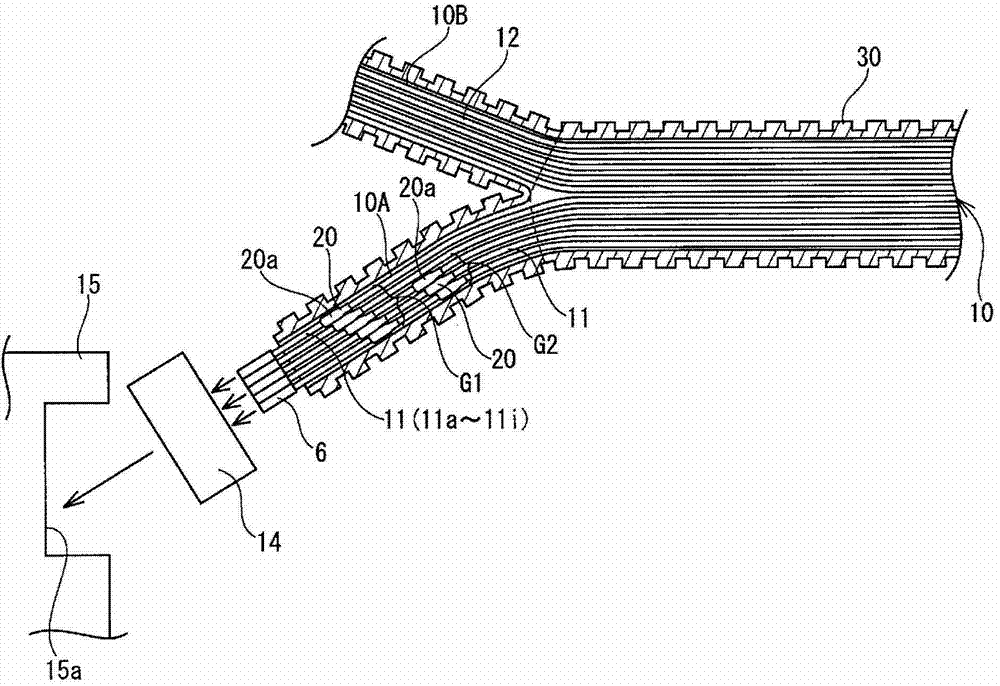
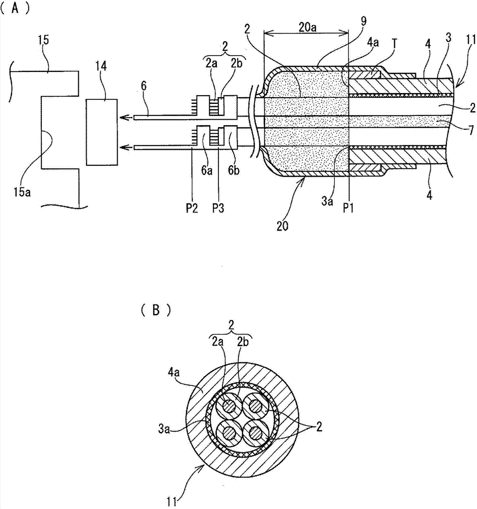
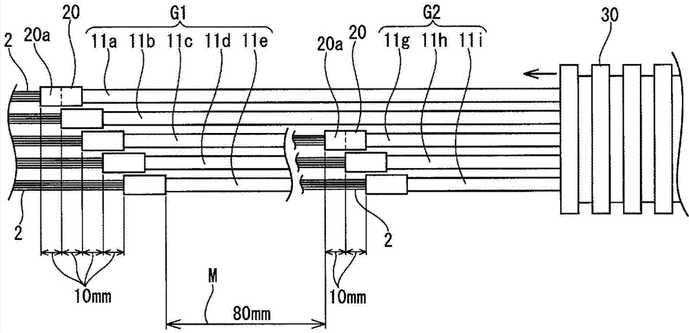
[0039] figure 1The wire harness 10 shown in is routed in the engine room of the car, which is an area exposed to water. A bundle of wires constituting the wire harness 10 includes a plurality of shielded wires 11 (eight wires in the present embodiment). The wire bundle includes electric wires 12 in addition to shielded wires 11 . On one end of the wire harness 10, terminals of eight shielded wires 11 are connected to a waterproof connector 14 connected to a connector fitting portion 15a of an ECU (Electronic Control Unit) 15 installed in the engine room . Another waterproof connector (not shown in the drawings) is connected to a normal electric wire 12 other than the shielded wire 11 . Specifically, one end portion of the wire harness 10 is branched into a branch wire 10A in which the eight shielded wires 11 are bundled and a branch wire 10B of another wire bundle.

[0040] ...


PUM

PropertyMeasurementUnit
lengthaaaaaaaaaa

Abstract

Provided is a wire harness that suppresses the hardening of waterproofing parts and the enlargement of the outer diameter thereof. In a group of cables configuring one wire harness, a plurality of shielded cables provided with waterproofing parts are divided into a plurality of groups, the positions of the waterproofing parts differ for each group, a prescribed distance is provided between waterproofing parts of different groups, and the waterproofing parts are distributed in the axial direction of the wire harness.

Description

technical field [0001] The present invention relates to a wire harness waterproof structure, and in particular, the invention relates to a wire harness waterproof structure that prevents a decrease in flexibility of a waterproof portion and reduces an increase in outer diameter. Background technique [0002] An increasing number of shielded wires are used to prevent noise from wire bundles in wire harnesses that are routed in automobiles. like Figure 5 As shown in , such a shielded wire includes a plurality of core wires 2 each having a strand 2 a covered by an insulating layer 2 b , a shield 3 and an outer casing (sheath) 4 . The core wire 2 is used as a signal wire. The shielding layer 3 is a tube composed of a metal braid covering the outer periphery of the bundled core wires 2 or a metal foil tape wound around the outer periphery. The case 4 is an insulating resin layer provided on the outer periphery of the shield layer 3 . In addition, in the case where the shieldi...

Claims


Application Information

Patent Timeline
Patent Type & Authority Applications(China)
IPC IPC(8): H01B7/282H01B7/00H02G15/04
CPCH01B7/282H02G3/0468H01B7/2825H02G15/046Y02A30/14H01B7/285
Inventor 佐久间隆史
Owner SUMITOMO WIRING SYST LTD
Why Eureka
Try Eureka