Gas mixing and distributing structure of double-chamber or multi-chamber thin film deposition equipment

A technology of thin film deposition and gas mixing, applied in gaseous chemical plating, metal material coating process, coating, etc., can solve the problems of high cost, complex structure, large space occupation, etc., and achieve convenient installation and maintenance, low cost, The effect of taking up little space

Inactive Publication Date: 2013-05-29
PIOTECH CO LTD
View PDF9 Cites 8 Cited by
  • Summary
  • Abstract
  • Description
  • Claims
  • Application Information

AI Technical Summary

Problems solved by technology

[0003] U.S. patents related to mixed gas intake, such as the U.S. patent with a publication date of July 15, 2003 and a publication number of 6,591,850, and the publication date of a U.S. patent with a publication number of 6,758,591 on July 6, 2004, and a publication date of U.S. Patent Publication No. 7204155 on April 17, 2007, U.S. Patent Publication No. 2003176074 on Sept. 18, 2003, U

Method used


Image

  • Gas mixing and distributing structure of double-chamber or multi-chamber thin film deposition equipment
  • Gas mixing and distributing structure of double-chamber or multi-chamber thin film deposition equipment

Examples


Example Embodiment

[0016] The present invention will be described in further detail below with reference to the drawings.

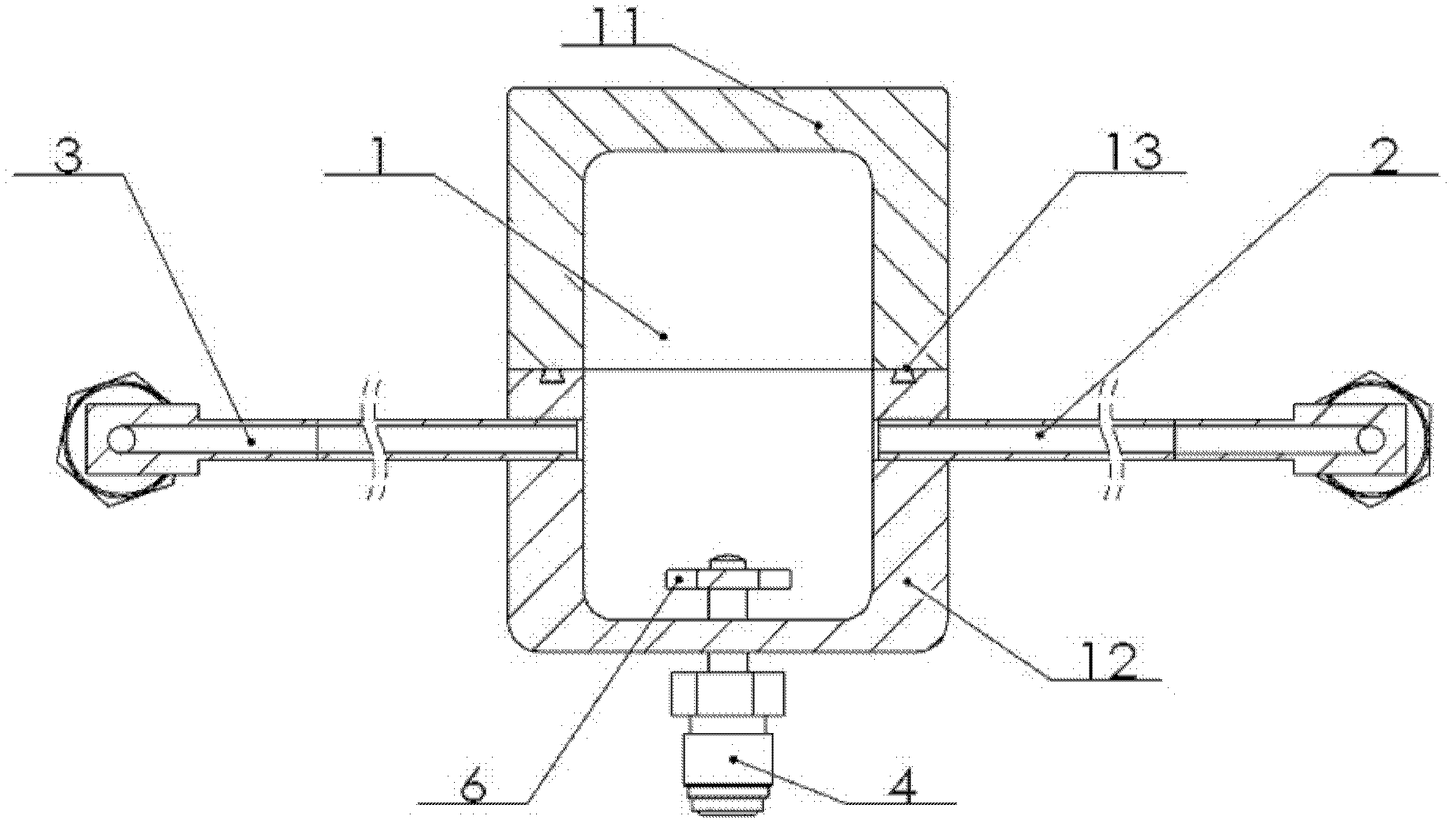
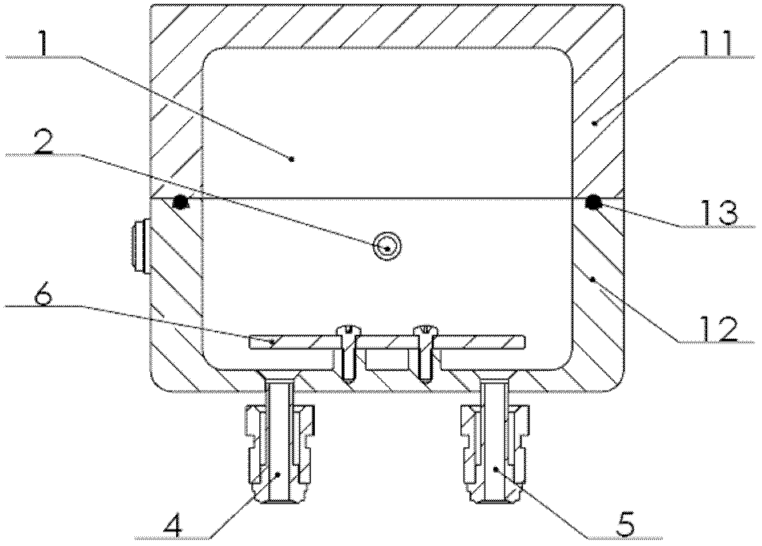
[0017] Such as figure 1 , figure 2 As shown, the present invention includes a gas mixing chamber 1, a gas inlet pipeline, a gas outlet pipeline, and an air inlet baffle 6. The gas mixing chamber 1 is an axisymmetric geometric body, such as a rectangular parallelepiped or a cylinder. The gas mixing chamber 1 can be The integrated structure can also be a horizontally split structure. The air mixing chamber 1 of this embodiment is a horizontally split structure, divided into an upper part 11 of the air mixing chamber and a lower part 12 of the air mixing chamber, and the middle is sealed by a sealing rubber ring 13 connection.

[0018] A first gas inlet pipe 4 and a second gas inlet pipe 5 are connected to the bottom surface of the lower half 12 of the gas mixing chamber. The first gas inlet pipe 4 and the second gas inlet pipe 5 are connected to the gas mixing chamber 1 respecti...


PUM


Abstract

The invention belongs to the field of semiconductor thin film deposition equipment and in particular relates to a gas mixing and distributing structure of double-chamber or multi-chamber thin film deposition equipment. The gas mixing and distributing structure comprises a gas mixing chamber, gas inlet pipelines, at least two gas outlet pipelines and a gas intake baffle, wherein the bottom surface of the gas mixing chamber is connected with the first gas inlet pipeline and the second gas inlet pipeline, the gas intake baffle which is arranged on the bottom surface of the gas mixing chamber is arranged above the first gas inlet pipeline and the second gas inlet pipeline, and the inlet of the first gas inlet pipeline and the inlet of the second gas inlet pipeline are respectively positioned below the gas intake baffle; and at least two gas outlet pipelines are symmetrically connected to two opposite side surfaces of the gas mixing chamber. According to the gas mixing and distributing structure, various process gases can be sufficiently mixed, gases among chambers are uniformly distributed, and therefore a same process state can be kept among the chambers; and in addition, the gas mixing and distributing structure is simple in structure, low in cost, small in size and convenient to install and maintain.

Description

technical field [0001] The invention belongs to the field of semiconductor thin film deposition equipment, in particular to a gas mixing and distribution structure of double chamber or multi-chamber thin film deposition equipment. Background technique [0002] The principle of thin film deposition technology is to place the wafer in a vacuum environment, inject an appropriate amount of reactive gas, and use the physical changes and chemical reactions of the gas to form a solid film on the surface of the wafer. [0003] U.S. patents related to mixed gas intake, such as the U.S. patent with the publication date of July 15, 2003 and the publication number 6591850, and the publication date of the U.S. patent with the publication number of 6758591 on July 6, 2004, the publication date is U.S. Patent Publication No. 7204155 on April 17, 2007, U.S. Patent Publication No. 2003176074 on Sept. 18, 2003, U.S. Patent Publication No. 2008202610 on Aug. 28, 2008 , the publication date is...

Claims


Application Information

Patent Timeline
IPC IPC(8): C23C16/455
Inventor 王丽丹梁学敏刘忆军
Owner PIOTECH CO LTD
Why Eureka
Try Eureka