
Temperature difference engine

A temperature difference engine, ambient temperature technology, applied in machines/engines, mechanical equipment, mechanisms that generate mechanical power, etc. Effect

Inactive Publication Date: 2013-05-29
杨健飞
View PDF6 Cites 4 Cited by
  • Summary
  • Abstract
  • Description
  • Claims
  • Application Information

AI Technical Summary

Problems solved by technology

[0005] The boiler plus turbine device is a one-way device. After the gas expands and drives the turbine, it cannot be directly circulated back to the boiler, which greatly reduces the utilization rate of heat energy.
Because of the utilization of heat energy, only the calorific value difference between the steam before and after the turbine is used, and the heat between the exhaust steam after the turbine and the normal temperature water before the boiler heating is wasted. Even if there are other heat recovery devices, it means It requires more cost input to recover part of the heat energy
On the other hand, the boiler plus turbine device is a popular equipment in thermal power plants at present. Only with such a high integration level can it be possible to obtain a relatively reasonable heat energy utilization rate, which prevents this heat energy utilization device from being popularized in Civil field
[0006] Although the Stirling engine has a high utilization rate of heat energy, because its power to push the piston comes from the "blow force" of the gas disturbing back and forth between the hot end and the cold end (located between the piston in the gas and the air wall There is a large gap between them), so that the output power is small, and it is difficult to meet the requirements of high-power output. There are few practical examples at present

Method used


Image

  • Temperature difference engine
  • Temperature difference engine
  • Temperature difference engine

Examples


Embodiment Construction

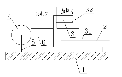
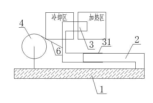
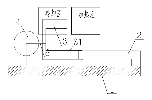
[0021] This embodiment provides a temperature difference engine, such as Figure 1 to Figure 4 As shown, they are schematic diagrams of four working states of the temperature difference engine of the present embodiment:

[0022] The thermoelectric engine includes a movable cylinder 3 filled with gas (which includes two parts of an air cavity body 32 and a cylinder 31), a fixed piston 2, a flywheel 4 as an energy transmission and conversion device, and is used to fix the fixed piston 2. And the fixed base 1 of the flywheel 4, and the heating zone and cooling zone placed at the two ends of the moving cylinder 3.

[0023] The air cavity body 32 is a heating and cooling induction area. The inner wall of the cylinder 31 is connected with the fixed piston 2. The fixed piston 2 can move in the cylinder 31 and seal the movable cylinder 3. The heating zone and the cooling zone are respectively located at two ends of the movement range of the air chamber body 32 . The rotating shaft o...


PUM


Abstract

The invention relates to a temperature difference engine which comprises a moving air cylinder, a fixed piston, a mechanical power outputting device, a fixed base of the mechanical power outputting device, an air cylinder heating zone and an air cylinder cooling zone. The moving air cylinder is connected with the fixed piston. When air in the moving cylinder is heated, expanded air pushes the piston so that the air cylinder leaves the heating zone for the cooling zone. When the air in the air cylinder is cooled, air thermal contraction is exerted on the fixed piston so that the moving air cylinder leaves the cooling zone for the heating zone. The process is repeated in circulation and motion power is output. The temperature difference engine is simple in structure, low in cost and especially suitable for solar energy utilization. Multiple engines can be used by being linked in series and in parallel.

Description

technical field [0001] The invention relates to the field of energy utilization, and is an engine device that converts thermal energy into mechanical energy and then into electrical energy. Background technique [0002] Since Watt invented the steam engine, converting heat energy into mechanical energy has become the most important energy utilization method for human beings. [0003] Boiler plus turbine structural device is currently the most common device for converting thermal energy into mechanical energy. It heats water from normal temperature to a steam state, uses the volume expansion of steam to drive a turbine, and outputs mechanical energy. [0004] Another small device is the Stirling engine invented more than a hundred years ago. The Stirling engine uses the contraction and expansion of the gas between the hot and cold ends to generate disturbances, pushes (blows) the piston in the gas, and outputs power. [0005] The boiler plus turbine device is a one-way dev...

Claims


Application Information

Patent Timeline
IPC IPC(8): F03G7/04
Inventor 杨健飞
Owner 杨健飞
Learn More