
Hot plate of metal fiber felt liquid absorption cores

A technology of metal fiber felt and metal fiber, which is applied in the field of heat exchange equipment, can solve problems such as the structure of the liquid-absorbing core is easily damaged, the capillary pressure head is small, and the liquid reflux resistance is large, so as to increase the bonding strength and contact area, and achieve good capillary Force and permeability, the effect of small liquid return resistance

Inactive Publication Date: 2013-05-29
辽宁三维传热技术有限公司 +1
View PDF7 Cites 7 Cited by
  • Summary
  • Abstract
  • Description
  • Claims
  • Application Information

AI Technical Summary

Problems solved by technology

[0004] Wire mesh liquid wick can get high heat transfer performance, but the manufacturing process repeatability is poor
[0005] Groove-type liquid-absorbing core has the advantages of small channel liquid flow resistance, but its capillary pressure head is small, heat transfer is small and other disadvantages, and it has high requirements for groove depth and width, and the directionality of the hot plate is very strong; When the groove has a large bend, the heat transfer performance of the hot plate is greatly reduced, the anti-gravity performance is poor, and its processing technology is complicated
[0006] The powder sintered liquid-absorbent core has the advantages of large capillary suction force and large heat transfer, but there is a contradiction that the capillary pressure increases while the liquid return resistance increases; the powder sintered liquid-absorbent core has low porosity and cannot be controlled. The backflow resistance is large, the structure of the liquid-absorbing core is easily damaged, and the sintered layer is thick, resulting in a large thermal resistance

Method used


Image

  • Hot plate of metal fiber felt liquid absorption cores
  • Hot plate of metal fiber felt liquid absorption cores
  • Hot plate of metal fiber felt liquid absorption cores

Examples


Embodiment Construction

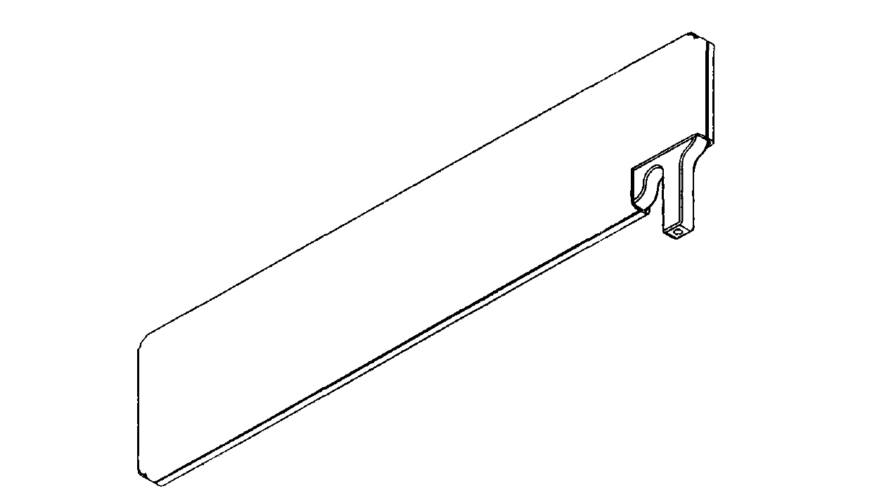
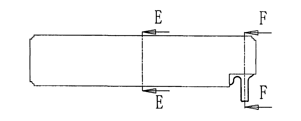
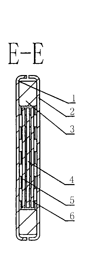
[0042] Figure 1A It is a schematic diagram of the three-dimensional structure of the hot plate of the metal fiber felt liquid-absorbing core of the present invention; Figure 1B It is a schematic diagram of the overall structure of the hot plate of the metal fiber felt liquid-absorbing core of the present invention; Figure 1C yes Figure 1B E-E direction sectional schematic diagram of ; Figure 1D yes Figure 1B The schematic diagram of the F-F direction section. It can be seen from the figure that the hot plate of the metal fiber felt liquid-absorbing core of the present invention is in the shape of a long straight plate, mainly including a sealed casing, a first metal fiber felt liquid-absorbing core 5, a second metal fiber felt liquid-absorbing core 6, and a support frame 4 and heat-conducting liquid working medium, the support frame 4, the first metal fiber felt liquid-absorbing core 5, and the second metal fiber felt liquid-absorbing core 6 are installed inside the s...


PUM

PropertyMeasurementUnit
diameteraaaaaaaaaa
diameteraaaaaaaaaa
diameteraaaaaaaaaa

Abstract

The invention discloses a hot plate of metal fiber felt liquid absorption cores, and belongs to the technical field of heat exchange equipment using a middle heat transfer medium or a middle heat transfer body. The hot plate comprises a sealed shell body, a first metal fiber felt liquid absorption core, a second metal fiber felt liquid absorption core, a supporting frame and heat conduction liquid working medium. The supporting frame, the first metal fiber felt liquid absorption core and the second metal fiber felt liquid absorption core are installed in the sealed shell body. The heat conduction liquid working medium is filled in the sealed shell body. Compared with the prior art, the hot plate has the advantages that the metal fiber felt liquid absorption cores have good capillary force and permeability, combination strength and contact areas between fibers are increased, large quantities of three-dimensional net-shaped porous structures are formed among the fibers, the porosity is high, specific areas are large, liquid backflow resistance is little, the backflow speed of the liquid working medium in the hot plate is beneficially improved, and therefore heat dissipation performance of the hot plate is improved.

Description

technical field [0001] The invention belongs to the technical field of heat exchange equipment utilizing an intermediate heat transfer medium or an intermediate heat transfer body, and more specifically, belongs to a heat plate whose liquid-absorbing core material is metal fiber felt. Background technique [0002] The flat hot plate in the prior art generally includes a sealed shell, a liquid-absorbing core, and a heat-conducting working fluid. The sealed shell is a plate-shaped hollow structure, and the liquid-absorbing core is welded on the inner surface of the sealed shell. Its working principle is: the sealed inner cavity of the sealed shell is filled with heat-conducting working medium, and the heat-conducting working medium is absorbed by the capillary adsorption force of the liquid-absorbing core installed in the inner cavity of the sealed shell. When the heating element connected to the radiator is working , the generated heat is transferred to the radiator, and the...

Claims


Application Information

Patent Timeline
Patent Type & Authority Applications(China)
IPC IPC(8): F28D15/04F28F21/08
Inventor 张洪坤
Owner 辽宁三维传热技术有限公司
Learn More