
Precise automatic gear grinding machine with saw

A gear grinding machine and band saw technology, which is applied to metal sawing equipment, tool dressing of sawing machine devices, and duplication process control systems, etc., can solve the problems of low work efficiency, poor tooth grinding effect, and high manufacturing cost. Simple structure, high grinding precision and high working efficiency

Inactive Publication Date: 2013-06-05
东莞市长盛刀锯有限公司
View PDF5 Cites 8 Cited by
  • Summary
  • Abstract
  • Description
  • Claims
  • Application Information

AI Technical Summary

Problems solved by technology

After milling the teeth, it is generally necessary to grind the band saw blade through a gear grinding machine. The existing gear grinding machine uses a fixed motor and a grinding wheel combination to grind the band saw blade. This structure of the gear grinding machine realizes the high efficiency of the band saw blade. However, there are many defects and deficiencies. Its structure is complex, its manufacturing cost is high, and it cannot be ground according to the tooth shape of the band saw blade. One tooth shape needs to be ground many times, and automatic tooth grinding cannot be realized. It is suitable for Limited range, poor gear grinding effect, and low work efficiency

Method used


Image

  • Precise automatic gear grinding machine with saw
  • Precise automatic gear grinding machine with saw
  • Precise automatic gear grinding machine with saw

Examples


Embodiment Construction

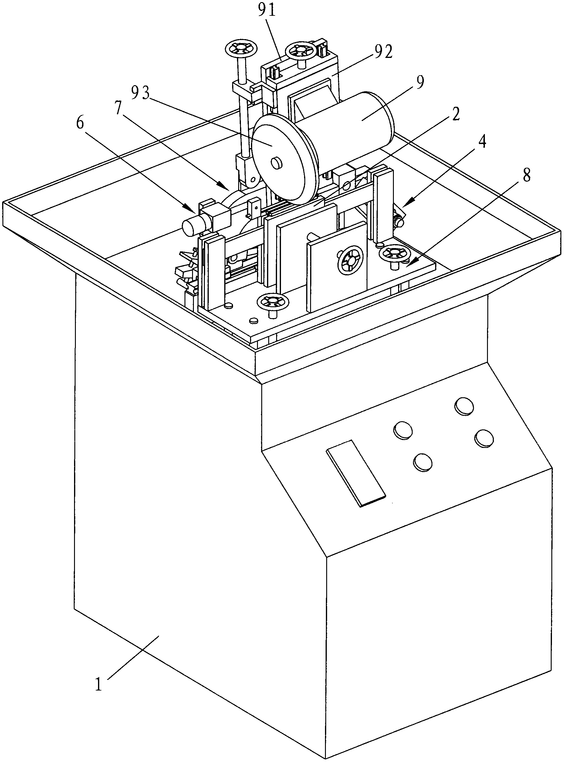
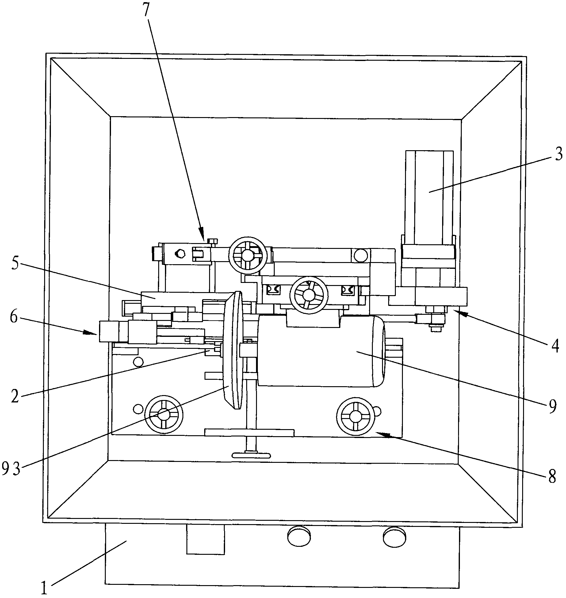
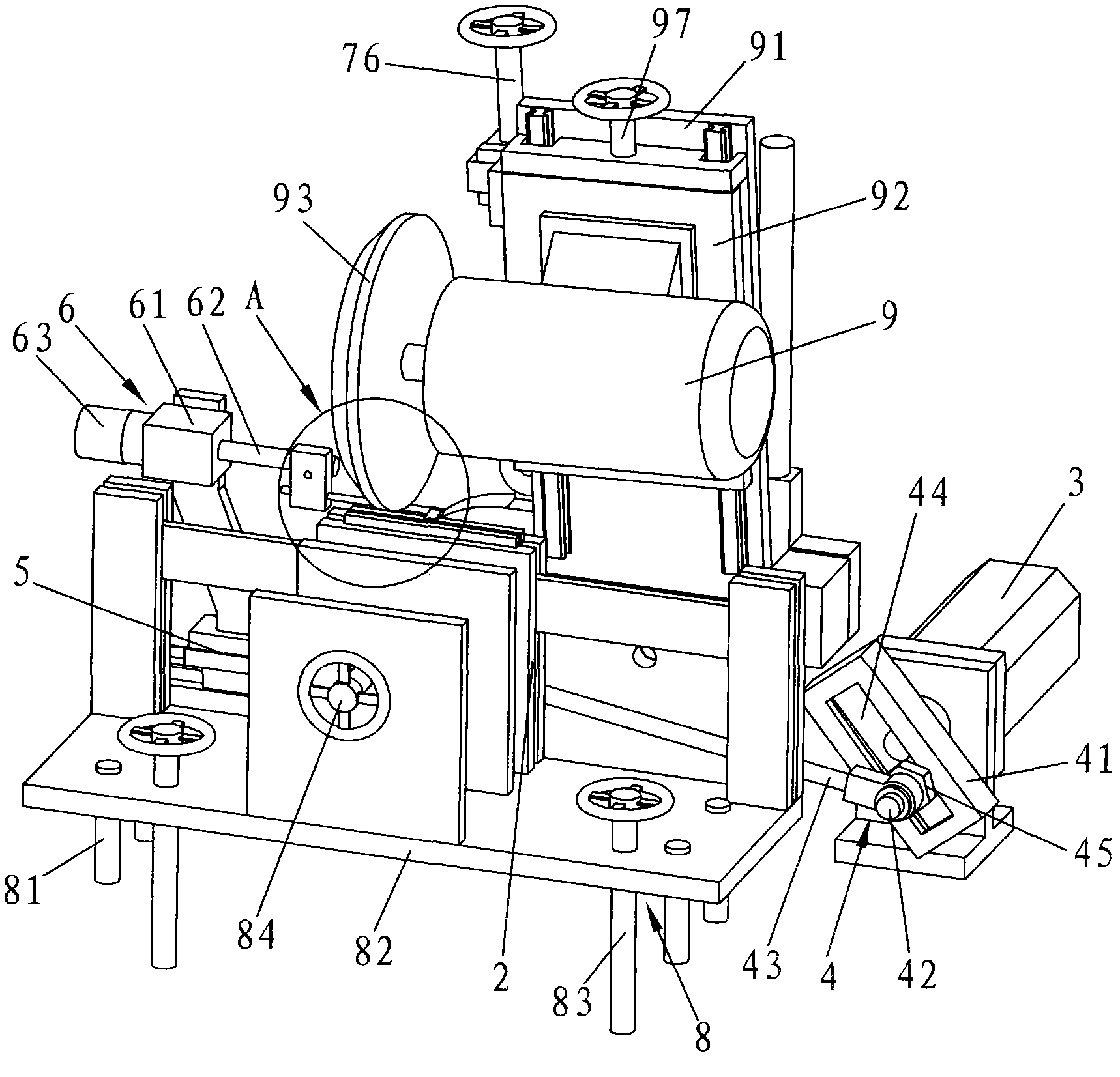
[0021] Below in conjunction with accompanying drawing, the present invention will be further described, see Figure 1~6 As shown, the precision band saw automatic gear grinding machine of the present invention includes a frame 1, and the top of the frame 1 is provided with a material clamping seat 2 with a material clamping groove 21, a stepless speed regulation drive motor 3, an eccentric mechanism 4, a sliding The sliding seat 5 that is arranged on the frame 1, the motor sliding seat 91, the motor mounting plate 92 that is slidably connected on the motor sliding seat 91, the gear grinding motor 9 that is fixed on the motor mounting plate 92, the gear grinding motor 9 that is arranged on the output The tooth grinding wheel 93 at the end, the pusher device 6 positioned at one side of the clamping tank 21, the grinding gear grinding wheel 93 is located above the clamping tank 21, the output shaft of the driving motor 3 is connected to the sliding seat 5 through the eccentric mec...


PUM


Abstract

The invention relates to the technical field of machining equipment with band saw blades, in particular to a precise automatic gear grinding machine with a saw. The precise automatic gear grinding machine comprises a machine frame, a material-clamping seat with a material clamping groove, a stepless speed regulating driving motor, an eccentric mechanism, a sliding seat, a motor sliding seat, a motor installation plate, a gear grinding machine, a gear grinding sand wheel and a material pushing device. The gear grinding sand wheel is located above the material clamping groove, an output shaft of the driving motor is connected with the sliding seat through the eccentric mechanism, the material pushing device is connected with the sliding seat, and the motor installation plate is connected with the sliding seat through a tooth-assembling-shaped device. By means of combination movements of the tooth-assembling-shaped device and the material pushing device, the precise automatic gear grinding machine with the saw enables the gear grinding sand wheel to perform automatic grinding according to tooth shapes of the ban saw blade. A circulating water system is adopted for cooling, high temperature cannot be caused at the ground positions, and the precise automatic gear grinding machine with the saw is high in gear grinding precision and working efficiency and simple in structure.

Description

Technical field: [0001] The invention relates to the technical field of band saw blade processing equipment, in particular to a precision band saw automatic gear grinding machine. Background technique: [0002] Band saw blades are widely used in machinery manufacturing, metallurgy, chemical industry, military industry and other industries. Band saw blades are generally processed through milling, splitting, quenching, tempering, surface treatment and other processes. After milling the teeth, it is generally necessary to grind the band saw blade through a gear grinding machine. The existing gear grinding machine uses a fixed motor and a grinding wheel combination to grind the band saw blade. This structure of the gear grinding machine realizes the high efficiency of the band saw blade. However, there are many defects and deficiencies. Its structure is complex, its manufacturing cost is high, and it cannot be ground according to the tooth shape of the band saw blade. One tooth...

Claims


Application Information

Patent Timeline
Patent Type & Authority Applications(China)
IPC IPC(8): B23D63/12B23Q35/04
Inventor 张德华
Owner 东莞市长盛刀锯有限公司
Learn More