

Spot welding device for connecting copper sheet with copper-clad ceramic substrates
A technology of copper-clad ceramic substrate and spot welding equipment, applied in welding equipment, auxiliary welding equipment, welding/cutting auxiliary equipment, etc. High-precision, easy-to-use effects
- Summary
- Abstract
- Description
- Claims
- Application Information
AI Technical Summary
Problems solved by technology
Method used
Image

Examples
Embodiment Construction
[0017] Below in conjunction with accompanying drawing, the present invention is described further.
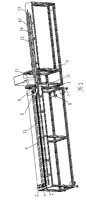
[0018] like figure 1 As shown, a spot welding equipment for connecting copper sheets and copper-clad ceramic substrates includes a dragging and absorbing mechanism, an electric welding machine 15 and a conveying mechanism. The dragging and absorbing mechanism includes a first base bracket 1, a servo motor 2, and a bearing seat 3. Bearings, guide rails 11, rotating shafts, belts 4, connecting plates 5, magnets 6, two bearing seats 3 are arranged symmetrically above the base bracket 1, and the output shaft 9 of the servo motor 2 is mounted on one of the bearing seats 3 through bearings Inside, the rotating shaft is installed in another bearing seat 3 through a bearing, the output shaft 9 and the rotating shaft are connected by a belt 4, one end of the connecting plate 5 is fixedly connected with the belt 4, and the other end of the connecting plate 5 is installed There are 6 mag...
PUM
 Abstract
Description
Claims
Application Information