Decorating strip caulking groove automatic groove cutting machine and processing technology

A technology for decorative strips and grooving machines, used in metal processing and other directions, can solve the problems of affecting the appearance of insulating glass, high labor intensity, easy to skew and fall off, etc., and achieve the effect of saving raw materials, high degree of automation, and improving production capacity.

Active Publication Date: 2013-06-05
CHONGQING HANGXING GLASS TECH
View PDF5 Cites 11 Cited by
  • Summary
  • Abstract
  • Description
  • Claims
  • Application Information

AI Technical Summary

Problems solved by technology

In the past, the connection of decorative strips mostly used the plug-in cross connection method, but the efficiency was low, the operation was complicated, and it was easy to skew and fall off; therefore, the decorative strips are now clamped with each other to form a cross-shaped structure, but it is necessary to process grooves on the decorative strips to realize two decorative strips. The fitting of the strip groove and the groove, but at present, the grooves on the decorative strip are all done by hand, which is inefficient, labor-intensive, and low-precision, so it affects the appearance of the insulating glass

Method used


Image

  • Decorating strip caulking groove automatic groove cutting machine and processing technology
  • Decorating strip caulking groove automatic groove cutting machine and processing technology
  • Decorating strip caulking groove automatic groove cutting machine and processing technology

Examples


Embodiment Construction

[0025] Below in conjunction with accompanying drawing and embodiment the present invention will be further described:

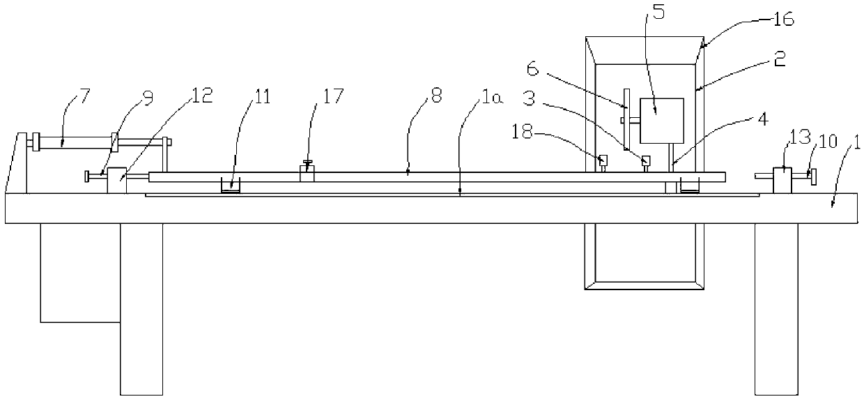
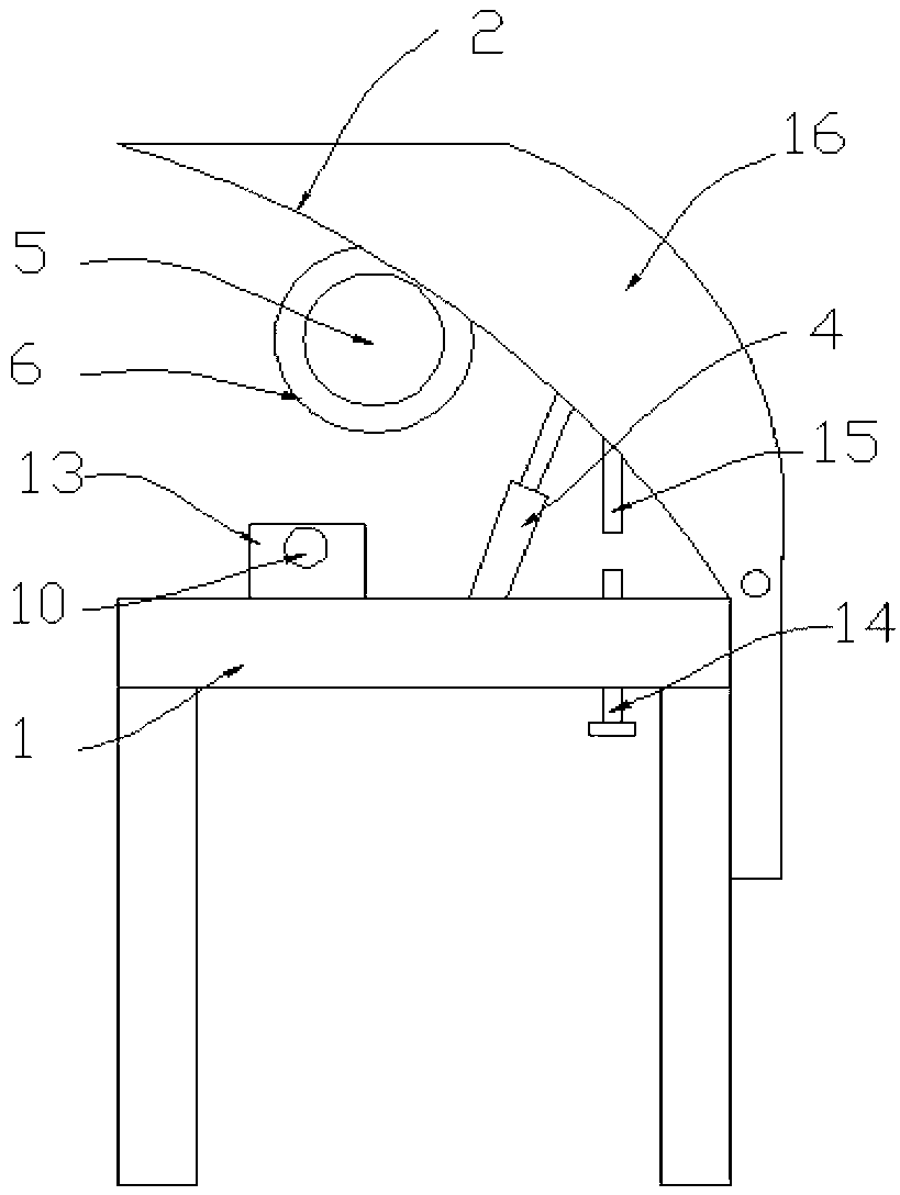
[0026] Such as figure 1 , figure 2 The shown automatic groove cutting machine for decorative strip embedding includes a workbench 1, a cutting frame 2 is hinged on one side of the workbench 1, a rotating shaft is installed on the workbench 1, and the cutting frame 2 Set on the rotating shaft, so the cutting frame 2 can rotate around the rotating shaft, a lower saw cylinder 4 is installed between the cutting frame 2 and the workbench 1, and the cylinder body of the lower saw cylinder 4 is fixed on the On the workbench 1, the piston rod of the saw cylinder 4 is connected to the cutting frame 2, a cutting motor 5 is fixed on the cutting frame 2, and a cutting saw 6 is fixedly sleeved on the output shaft of the cutting motor 5. , start the saw cylinder 4, the cutting frame 2 can be moved up or down, so as to ensure that the cutting saw 6 gives way and cuts the...


PUM


Abstract

The invention discloses a decorating strip caulking groove automatic groove cutting machine. The decorating strip caulking groove automatic groove cutting machine comprises a working table, and is characterized in that, a cutting machine frame is hinged on one side of the working table, a sawing air cylinder is installed between the cutting machine frame and the working table, a cylinder body of the sawing air cylinder is fixed on the working table, a piston rod of the sawing air cylinder is connected with the cutting machine frame, a cutting motor is fixed on the cutting machine frame, a cutting saw is fixedly sleeved on an output shaft of the cutting motor, a feed regulating mechanism is fixed on the working table, and the feed regulating mechanism is located below the cutting saw. The invention further discloses a decorating strip caulking groove processing technology. The decorating strip caulking groove processing technology is characterized by including the following steps: blanking; clamping; setting groove width; setting groove depth; opening a groove and fetching pieces. The decorating strip caulking groove automatic groove cutting machine and the decorating strip caulking groove processing technology have the advantages of being high in machining precision, ensuring satisfying technological requirements, improving production capacity, improving work efficiency by 10 times compared with the prior handcrafted art, reducing rejection rate, saving raw materials, and being low in cost, high in automaticity, easy to achieve and the like.

Description

technical field [0001] The invention relates to a decorative strip processing equipment, in particular to an automatic slotting machine for embedding a decorative strip and a processing technology thereof. Background technique [0002] Energy-saving decorative insulating glass is an energy-saving product widely used in the field of high-end buildings. It is an energy-saving and emission-reducing product vigorously advocated and encouraged by the state. Various strip decorations are embedded in the insulating glass, and the energy-saving insulating glass is endowed with beautiful decoration. It plays an important aesthetic role in beautifying the environment and life. In the past, the connection of decorative strips mostly used the plug-in cross connection method, but the efficiency was low, the operation was complicated and it was easy to skew and fall off; therefore, the decorative strips are now connected to each other to form a cross-shaped structure, but it is necessary ...

Claims


Application Information

Patent Timeline
Patent Type & Authority Applications(China)
IPC IPC(8): B26D3/06B26D7/06B26D7/02
Inventor 李俊
Owner CHONGQING HANGXING GLASS TECH
Why Eureka
Try Eureka