
Strip self-centering detecting method based on infrared ray

A technology of automatic alignment and detection method, which is applied in the direction of measuring device, winding strip, and optical device. , the effect of good overall position

Active Publication Date: 2015-06-24
XIAN UNIV OF TECH
View PDF6 Cites 0 Cited by
  • Summary
  • Abstract
  • Description
  • Claims
  • Application Information

AI Technical Summary

Problems solved by technology

[0008] The purpose of the present invention is to provide a strip automatic centering detection method based on infrared light, which solves the problem that the existing detection methods all use the principle of parallel light for detection, the detection accuracy is not high enough, the detection range is limited, and the limitations are relatively large. question

Method used

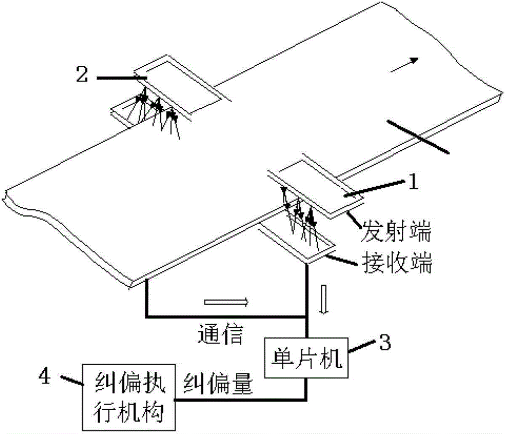
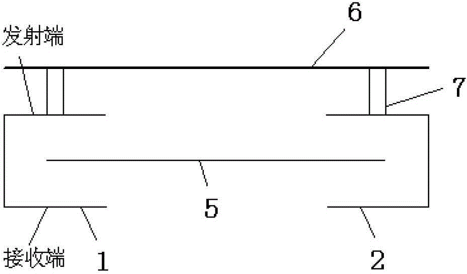
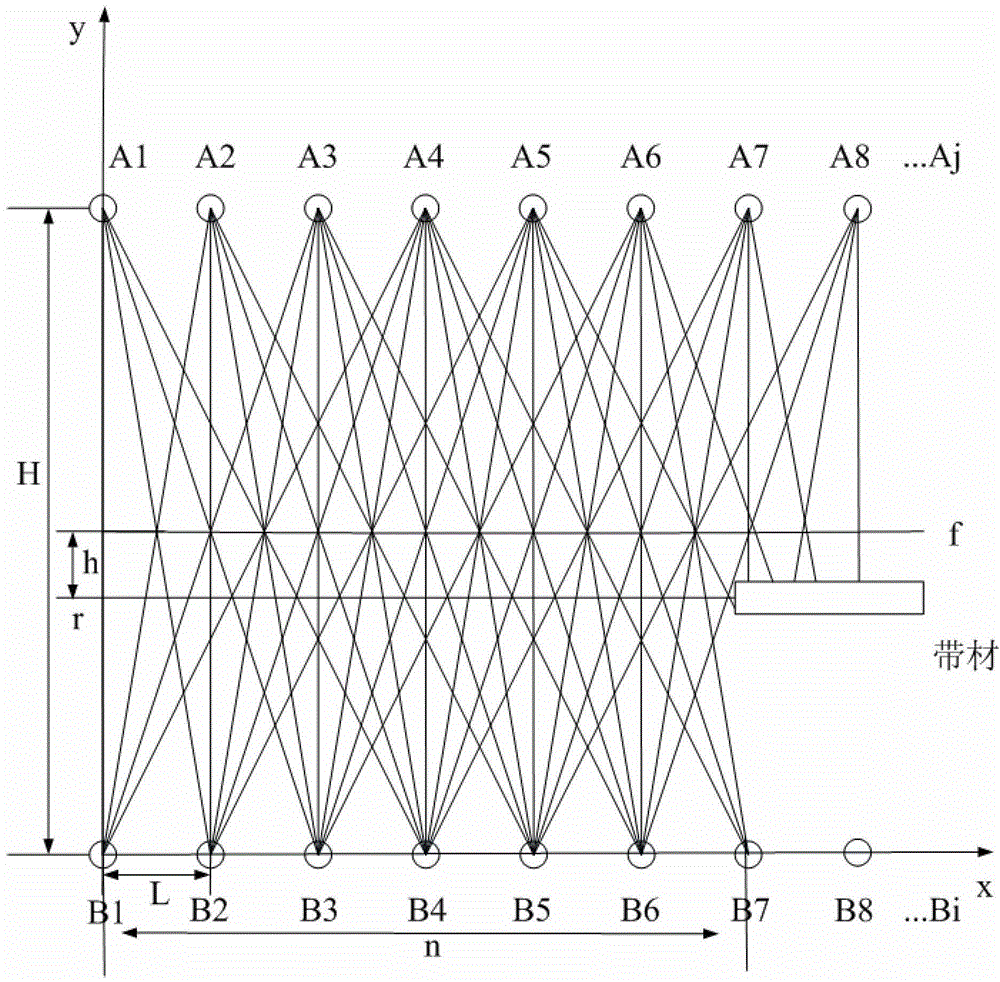

Image

  • Strip self-centering detecting method based on infrared ray
  • Strip self-centering detecting method based on infrared ray
  • Strip self-centering detecting method based on infrared ray

Examples


Embodiment Construction

[0019] The detection method of the present invention is different from the sensor detection method on the market now, and the meanings of the inspection precision, inspection range and distance are explained as follows:

[0020] Detection accuracy: established as image 3 In the coordinate system shown, it is possible to know the emission light equation of all luminous tubes and the coordinates of the intersection with the position equation of the strip. Among all the intersection coordinates, the maximum value of the difference between adjacent coordinates is the detection error of the system, that is, the detection accuracy . When the position of the strip changes, the coordinates of the intersection point will change, and the detection accuracy will change with the position of the strip.

[0021] Detection range: the maximum range that the detection device can detect when the position of the strip changes.

[0022] Detection distance: the distance between the photoelectri...


PUM


Abstract

The invention discloses a strip self-centering detecting method based on infrared ray. The specific process includes: step 1 (collecting information), when the strip shifts with lateral deviations between infrared transmitting tubes and infrared receiving tubes, signals transmitted from relevant infrared transmitting tubes are blocked, and the changing messages are transmitted to a single chip in a communication manner through the infrared receiving tubes; step 2 (processing information), when the single chip receives the changing messages of state signals of the infrared receiving tubes, according to a rectangular coordinate system set up with all position parameters of the infrared transmitting tubes and the infrared receiving tubes, all transmitting ray equations of the infrared transmitting tubes and position equations of the strip are obtained, border position parameters of the strip are obtained through operations, whether the strip deviates from a preset central line or not can be judged by comparisons, and meanwhile position deviation-correcting values are sent to a deviation-correcting mechanism to realize centering. The strip self-centering detecting method is wide in detecting range, good in stability and high in anti-interference capability.

Description

technical field [0001] The invention belongs to the technical field of automatic detection and uses infrared light to detect the edge displacement of a non-contact and opaque strip, in particular to an automatic centering detection method for a strip based on infrared light. Background technique [0002] With the development of the processing industry, not only the demand for metal strips is increasing, but also higher requirements are put forward for metal strips, that is, chemical composition, mechanical properties, dimensional tolerances, and appearance shapes are all controlled within a narrow range. Within the range, only such a strip can guarantee the stability of the production process, the least material consumption, the highest yield and low processing cost. During the coiling and unwinding of strip-shaped articles in printing, papermaking, coating, plastic film, steel rolling and other industries, due to the irregular winding of the previous process or the deviatio...

Claims


Application Information

Patent Timeline
Patent Type & Authority Patents(China)
IPC IPC(8): B65H26/00B65H23/032G01B11/00
Inventor 郑岗余雪郑健楠
Owner XIAN UNIV OF TECH
Learn More