
Underground gas storage well wall automation comprehensive detection system and detection method

A technology for comprehensive detection and gas storage wells, which is applied to the analysis of solids using sonic/ultrasonic/infrasonic waves. Equipment configuration, the effect of reducing the failure rate

Active Publication Date: 2013-06-05
山东省特种设备检验研究院鲁特检验检测有限公司 +1
View PDF8 Cites 18 Cited by
  • Summary
  • Abstract
  • Description
  • Claims
  • Application Information

AI Technical Summary

Problems solved by technology

[0003] At present, domestically, ultrasonic technology is used as the main method for gas storage well casing inspection, but the detection method used is limited to the detection of wall thickness corrosion, and the detection of another key defect—crack defect is not involved, which results in The detection of gas storage wells is not comprehensive, and it is easy to miss some key defects, resulting in potential safety hazards
On the other hand, in the existing equipment, the downhole equipment and the uphole equipment adopt optical fiber transmission. Although the optical fiber transmission has the advantages of fast transmission speed and large amount of transmitted data, the optical fiber is too fragile in the field operation, and it is easy to cause damage during the operation. In addition to the optical fiber, cables for transporting the detector to the underground are also required, so that one set of equipment needs to be equipped with two sets of cables and two sets of wire rollers, which increases the complexity of the equipment

Method used


Image

  • Underground gas storage well wall automation comprehensive detection system and detection method
  • Underground gas storage well wall automation comprehensive detection system and detection method
  • Underground gas storage well wall automation comprehensive detection system and detection method

Examples


Embodiment 1

[0035] Embodiment 1 The ultrasonic probe group 13 includes a wall thickness corrosion detection probe group 131 and a crack detection probe group 132, the two probe groups are arranged up and down and located in the same cavity, which can be as follows Figure 5 As shown in -a, the crack detection probe group 132 is at the top, and the wall thickness corrosion detection probe group 131 is at the bottom, which can also be as follows Figure 5 As shown in -b, the crack detection probe group 132 is at the bottom, the wall thickness corrosion detection probe group 131 is at the top, and the probes of each probe group are arranged circumferentially along the circumferential direction of the cavity. Wall thickness corrosion detection and crack detection are carried out simultaneously in one downhole test.

Embodiment 2

[0036] Embodiment 2 The ultrasonic probe set 13 includes a wall thickness corrosion detection probe set 131 and a crack detection probe set 132, and the two probe sets are respectively located in two cavities. Figure 5 -a is the cavity where the crack detection probe group 132 is located, Figure 5 -b is the chamber where the wall thickness corrosion detection probe group 131 is located, and the probes of each probe group are arranged circumferentially along the circumference of the chamber. Wall thickness corrosion detection and crack detection are completed in two downhole tests.

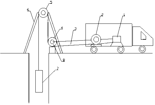
[0037] Before using the above-mentioned detection system, each device is installed. The upper computer 1, the DC power supply 10, and the cable roller 2 are located in the detection vehicle, and the operator operates the detection system on the vehicle. Pass the cable around the two rollers of the lifting device in turn, and support the roller b5 directly above the wellhead, and place the roller...


PUM


Abstract

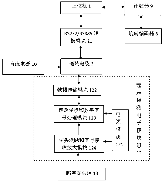
The invention relates to an underground gas storage well wall automation comprehensive detection system and a detection method. The system comprises an upper computer, a position measuring device, a cable lifting device, a direct current power supply and an underground movable detector, wherein the upper computer is placed on a well, and the movable detector is communicated with a device on the well through an armor cable and obtains power. Occupied space of the cable is saved, field operation is convenient, a wall thickness corrosion probe group and a flaw detection probe group are arranged inside the movable detector, detection for the wall thickness corrosion and flaws can be achieved simultaneously, and detection for the gas storage well is complete. Meanwhile, an underground device of the system integrates encouraging, receiving, amplification and signal processing and transmission functions, therefore ultrasonic signals does not need to be transmitted to the ground to be processed for a long distance, fidelity and the signal to noise ratio of the signals are greatly improved, and detection results are accurate.

Description

technical field [0001] The invention belongs to the field of ultrasonic detection of industrial gas storage wells, and in particular relates to an automatic comprehensive detection system and detection method for underground gas storage well wall thickness corrosion detection and crack detection of gas storage well walls. Background technique [0002] High-pressure underground gas storage well (hereinafter referred to as gas storage well) is a new type of gas storage equipment for CNG gas filling stations. It is a special tubular vertical pressure vessel installed underground for the purpose of storing compressed natural gas. The well body structure adopts Threaded (no welding) connection, working pressure up to 25MPa, has the advantages of small footprint, strong safety, low operating cost, and easy operation and maintenance. However, the gas storage well casing is buried deep underground (up to 260m deep). Due to formation electrochemistry, fatigue corrosion and othe...

Claims


Application Information

Patent Timeline
Patent Type & Authority Applications(China)
IPC IPC(8): G01N29/04
Inventor 张峰李剑左晓杰田卫星韩伟艾懿硕丁益鹏刘震徐方刚扈秀峰冯雪彬
Owner 山东省特种设备检验研究院鲁特检验检测有限公司
Learn More