Detecting device, power receiving device, contactless power transmission system, and detecting method
A detection device and detection part technology, applied in the direction of measuring devices, electromagnetic wave systems, radio wave measurement systems, etc., can solve the problems of high cost and imposing design restrictions, and achieve high metal foreign object detection, high precision, and realization of precision Effect
- Summary
- Abstract
- Description
- Claims
- Application Information
AI Technical Summary
Problems solved by technology
Method used
Image

Examples
no. 1 example
[0039] 2. First embodiment (detection section: an example including a resonance frequency adjuster and a first frequency remover)
[0040] 3. Second Embodiment (Separator: Example where a separator is provided on the load side of the resonance circuit)
[0041] 4. Third Embodiment (Frequency Remover: An Example in which a Second Frequency Remover is Provided Instead of a Separator)
[0042] 5. Other
[0043]
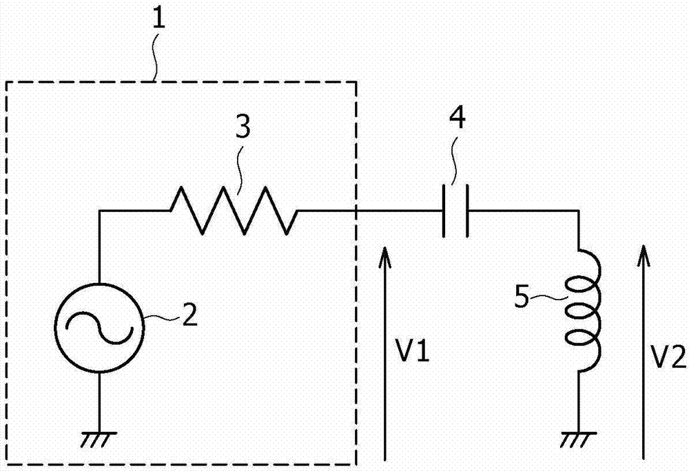
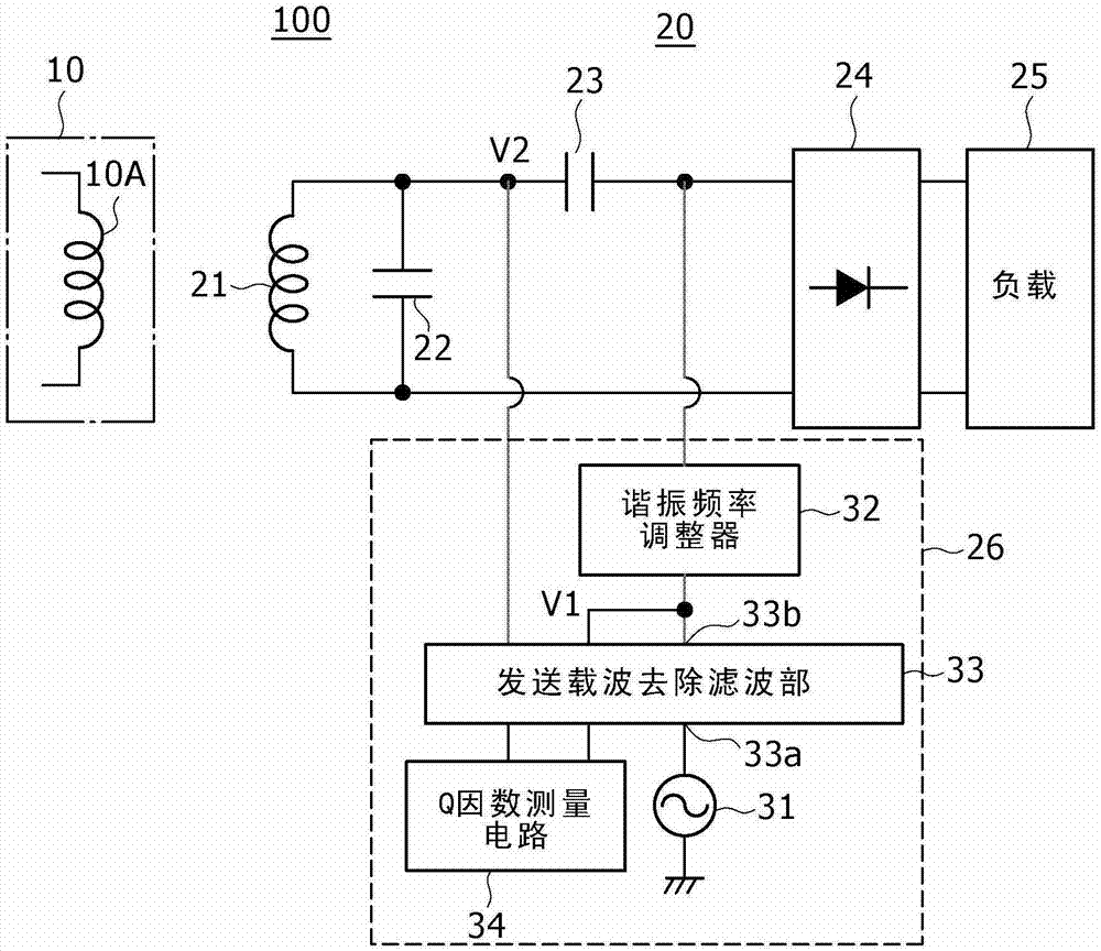
[0044] An embodiment of the present disclosure is a technique of measuring a quality factor (Q factor) of a circuit including a coil coupled to the outside when feeding power from a power transmitting side (primary side) to charge a power receiving side (secondary side); And based on the measurement result of the Q factor, it is judged whether there is a metal foreign object near the coil.
[0045] The Q factor is an index representing the relationship between energy retention and energy loss, and is generally used as a value representing the sharpness of the resonan...
no. 2 example
[0130] In order to accurately measure the Q factor of a resonant circuit, the impedance of the rectifier from the point of view of the resonant circuit should be high. For this purpose, as an example, the rectifier may be disconnected to be set in an open circuit state.
[0131] Therefore, in the second embodiment, the following example will be explained: for the power receiving device 20 according to the first embodiment (see figure 2 ) A separator for separating the load is provided so that the detection part can be separated from the load in Q factor measurement.
[0132] When the rectifier is disconnected, power cannot be received. However, even in this case, there is an advantage that the system does not need to go through a complicated control flow of stopping power transmission on the primary side. The power supply to the Q-factor measurement circuit in this case is driven by using the load 25 (battery, etc.) possessed on the secondary side or the charge stored in th...
no. 3 example
[0170] [Configuration example of power receiving device]
[0171] For example, when in figure 2 When the filter section is arranged in front of the rectifier 24 (resonant circuit side), although there is a possibility that the loss of the power transmission signal increases, the Q factor measurement can be performed without stopping the power reception.
[0172] Therefore, in the third embodiment, the power receiving device 20 according to the first embodiment (see figure 2 ) of the rectifier 24 (on the resonant circuit side) is provided with an example of a measurement signal removal filter unit 56 . This configuration makes the impedance on the rectifier side appear high to the Q-factor measurement signal.
[0173] Figure 15 is a circuit diagram showing a configuration example of a power receiving device according to a third embodiment of the present disclosure.
[0174] In the power receiving device 50 , a measurement signal removal filter section 56 is provided betw...
PUM
 Abstract
Description
Claims
Application Information
 - R&D
- Intellectual Property
- Life Sciences
- Materials
- Tech Scout
- Unparalleled Data Quality
- Higher Quality Content
- 60% Fewer Hallucinations
Browse by: Latest US Patents, China's latest patents, Technical Efficacy Thesaurus, Application Domain, Technology Topic, Popular Technical Reports.
© 2025 PatSnap. All rights reserved.Legal|Privacy policy|Modern Slavery Act Transparency Statement|Sitemap|About US| Contact US: help@patsnap.com