An Optimal Design Method for Engine Cooling System

An engine cooling and cooling system technology, applied in computing, special data processing applications, instruments, etc., can solve the problems of unrealizable modification, passive optimization of work, limited layout space, etc., to improve development efficiency, complete data, and low cost. Effect

Active Publication Date: 2016-03-16
CHERY AUTOMOBILE CO LTD
View PDF4 Cites 0 Cited by
  • Summary
  • Abstract
  • Description
  • Claims
  • Application Information

AI Technical Summary

Problems solved by technology

Engine cooling system bench and vehicle tests can only be carried out after the prototype is completed. At this time, if improper layout or unreasonable matching is found, due to the limited layout space, many modifications cannot be realized, and the optimization work is very passive.

Method used


Image

  • An Optimal Design Method for Engine Cooling System
  • An Optimal Design Method for Engine Cooling System
  • An Optimal Design Method for Engine Cooling System

Examples


Embodiment 1

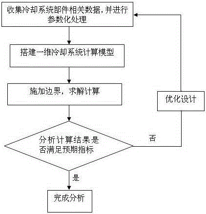
[0032]One of the expected design goals of the engine cooling system in one embodiment is that when the rated operating point of the water pump is the engine speed of 6000rpm, the water pump flow rate of 119l / min and the pressure rise of 120KPa will be satisfied, while another design goal is the engine speed of 2000rpm (idle speed Working condition), the flow rate of the warm air core should meet 8.9l / min. Bring the relevant data parameters of each component of the above engine cooling system into the above simulation model for simulation calculation, and combine the various working conditions (speed, etc.) to obtain the calculation results of the flow, temperature and pressure distribution of each component as shown in the table below:

[0033]

[0034] It can be seen that when the engine speed is 6000rpm, the flow rate of the water pump meets the requirements, but the calculated pressure rise of the water pump is 156.8KPa, which is higher than the target requirement of 120K...


PUM


Abstract

The present invention provides an optimal design method of an engine cooling system. The design method uses one-dimensional fluid simulation technology to analyze the flow of the cooling system, and includes the following steps: (1) collecting data related to cooling system components and performing parameterized processing; 2) Build a one-dimensional model; (3) Carry out simulation calculations under different working conditions; (4) Analyze the calculation results, and carry out routine optimization design of the cooling system according to the calculation results. The present invention obtains the optimal matching parameters of the engine cooling system by simulating the pressure distribution, flow distribution, flow resistance of each component, and temperature change of the cooling fluid in the warm-up condition at the initial stage of design, and can better guide the design of the cooling system and development to improve development efficiency and save test costs.

Description

technical field [0001] The invention relates to the technical field of automobile engine development, in particular to an engine cooling system optimization design method based on computer simulation calculation. Background technique [0002] The role of the engine cooling system is to dissipate part of the heat absorbed by the heated parts in time to ensure that the engine works at the most suitable temperature state, and when the external temperature is low, the heat absorbed by the coolant is used for heating the passenger compartment. Engine cooling system bench and vehicle tests can only be carried out after the prototype is completed. At this time, if improper layout or unreasonable matching is found, due to the limited layout space, many modifications cannot be realized, and the optimization work is very passive. Therefore, it is very important to predict and optimize the performance of the engine cooling system before the prototype trial production. Contents of the...

Claims


Application Information

Patent Timeline
Patent Type & Authority Patents(China)
IPC IPC(8): G06F17/50
Inventor 陶丽芳徐亚飞刘小生
Owner CHERY AUTOMOBILE CO LTD
Why Eureka
Try Eureka