Eureka AIR delivers breakthrough ideas for toughest innovation challenges, trusted by R&D personnel around the world.

Device for wafer bonding and wafer bonding method

A wafer bonding and wafer technology, applied in the direction of electrical components, semiconductor/solid-state device manufacturing, circuits, etc., can solve problems such as large differences, waste of time and energy, and reduce production efficiency, so as to optimize the bonding process, Reduced preparatory work and shortened bonding time

Active Publication Date: 2016-02-03
SHANGHAI MICRO ELECTRONICS EQUIP (GRP) CO LTD
View PDF5 Cites 0 Cited by
  • Summary
  • Abstract
  • Description
  • Claims
  • Application Information

AI Technical Summary

Problems solved by technology

[0004] The main disadvantages of the above-mentioned bonding process are as follows: First, for manual equipment, the time used for alignment and bonding is different and greatly different, resulting in inconsistent production beats. Bonding includes vacuuming, heating, pressing and powering, cooling , time is significantly longer than alignment - thus lower productivity; in addition, the operator will further reduce productivity (and introduce some alignment deviation) when transferring the wafer from the alignment equipment to the bonding equipment
Second, for automatic equipment, the alignment equipment and bonding equipment are usually combined on one equipment, and the wafer is transferred through the robot to reduce errors and improve production capacity, but it still does not solve the difference in the time used for alignment and bonding cause low production efficiency
Third, when traditional bonding equipment works, it is necessary to repeatedly perform the processes of vacuuming, heating, applying pressure and voltage, cooling, inflating and cooling in series. The production efficiency is low and a lot of time and energy are wasted.

Method used

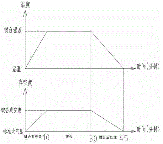
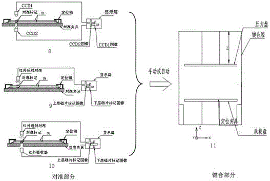

Image

  • Device for wafer bonding and wafer bonding method
  • Device for wafer bonding and wafer bonding method
  • Device for wafer bonding and wafer bonding method

Examples


Embodiment Construction

[0022] A wafer bonding apparatus according to a specific embodiment of the present invention will be described in detail below with reference to the accompanying drawings. However, the present invention should be understood as not limited to such embodiments described below, and the technical idea of ​​the present invention can be implemented in combination with other known technologies or other technologies having the same functions as those known technologies.

[0023] In the following description, in order to clearly show the structure and working method of the present invention, many directional words will be used to describe, but "front", "rear", "left", "right", "outer", "inner" should be used Words such as ", "outward", "inward", "upper" and "lower" are to be understood as convenient terms, and should not be understood as restrictive terms. In addition, the term "Y direction" used in the following description mainly refers to the direction parallel to the horizontal dir...


PUM


Abstract

The invention discloses a device for wafer bonding. The device comprises a first cavity for being aligned to a wafer, a second cavity for bonding the wafer, and a third cavity for cooling the wafer. The second wafer comprises a first port connected with the first cavity and a second port connected with the second cavity. The first cavity and the third cavity respectively comprise a port connected with the outside. The invention simultaneously discloses a wafer bonding method.

Description

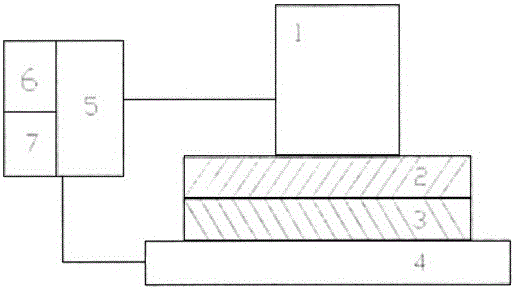
technical field [0001] The invention relates to the field of semiconductor manufacturing equipment, in particular to a wafer bonding device and a wafer bonding method. Background technique [0002] Wafer bonding technology can bond wafers of different materials together. Commonly used bonding technologies include: silicon-silicon direct bonding, silicon-glass direct bonding, metal diffusion bonding, polymer adhesive bonding, etc. This technology has been applied in many semiconductor fields, such as 3D-TSV, HB-LED, SOI, MEMS, etc. It is one of the important technologies for the future development of the semiconductor industry. [0003] According to different application fields, the process parameters of wafer bonding are different, but the basic principles are similar. A schematic diagram of the bonding process is shown in figure 1 As shown, in a vacuum environment, figure 1 The two silicon wafers 2 and 3 in the process apply a certain pressure through the pressure contro...

Claims


Application Information

Patent Timeline
Patent Type & Authority Patents(China)
IPC IPC(8): H01L21/603
Inventor 唐世弋
Owner SHANGHAI MICRO ELECTRONICS EQUIP (GRP) CO LTD
Why Eureka
Eureka Blog
Learn More