Connector structure and manufacture method thereof

A manufacturing method and connector technology, applied in the direction of connection, conductive adhesive connection, contact parts, etc., can solve the problems of reduced electrical reliability, limited thickness, damage, etc., and achieve the effect of reducing thickness

Active Publication Date: 2013-06-05
UNIMICRON TECH CORP
View PDF6 Cites 9 Cited by
  • Summary
  • Abstract
  • Description
  • Claims
  • Application Information

AI Technical Summary

Problems solved by technology

However, the part of the copper layer 150 located on the via hole 100c is easily damaged by the influence of the subsequent manufacturing process, or when the conductive elastic cantilever 130 is electrically connected with an external component, it may even break due to pressure, thereby causing electrical reliability. falling problem
[0006] In addition, since the connector structure 10 has the substrate 100, the thickness of the connector structure 10 is often limited by the thickness of the substrate 100 and cannot meet the current thinning requirements.

Method used


Image

  • Connector structure and manufacture method thereof
  • Connector structure and manufacture method thereof
  • Connector structure and manufacture method thereof

Examples


Embodiment Construction

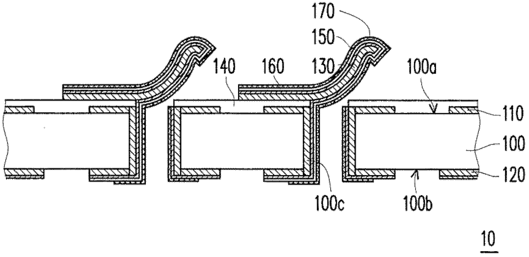
[0051] The connector structure of the present invention mainly includes an adhesive layer and a conductive elastic cantilever. The fabrication methods of the adhesive layer, the conductive elastic cantilever and the connector structure will be described below.

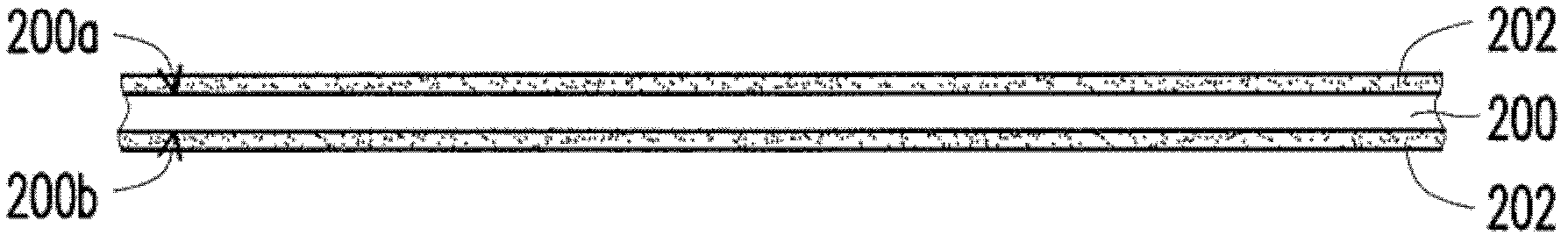
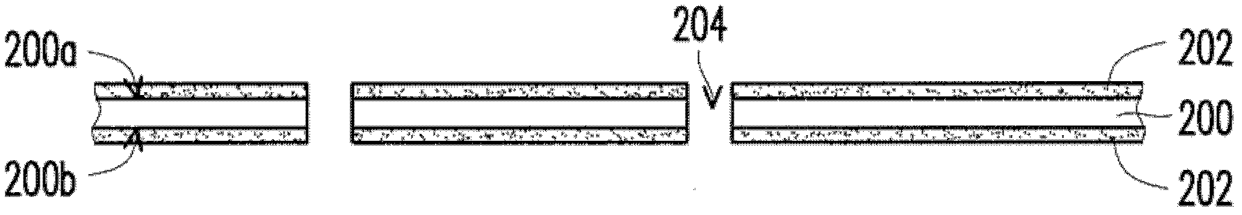
[0052] Figure 2A to Figure 2C It is a cross-sectional view of the manufacturing process of the adhesive layer of the connector structure shown according to the embodiment of the present invention. First, please refer to Figure 2A , providing an adhesive material layer 200 . The material of the adhesive material layer 200 is, for example, a low-flow adhesive dielectric layer. The adhesive material layer 200 has a first surface 200a and a second surface 200b opposite to each other. In addition, the first surface 200 a and the second surface 200 b of the adhesive material layer 200 respectively have a protection layer 202 . The protection layer 202 is, for example, a polyethylene terephthalate (PET) film.

[0053]...


PUM


Abstract

The invention discloses a connector structure and a manufacture method thereof. The connector structure comprises an adhesive coating, at least one first conductive elastic cantilever and at least one second conductive elastic cantilever. At least one through hole is formed in the adhesive coating, conductive resin is filled in the through hole, the first conductive elastic cantilever is arranged on a first surface of the adhesive coating in a matched mode, and the first conductive elastic cantilever is provided with a first fixed end portion and a first free end portion which is connected with the first fixed end portion, wherein the upper surface of the first free end portion is higher than the upper surface of the first fixed end portion, and the first fixed end portion is connected with the conductive resin. The second conductive elastic cantilever is arranged on a second surface of the adhesive coating in a matched mode and is provided with a second fixed end portion and a second free end portion which is connected with the second fixed end portion, wherein the upper surface of the second free end portion is higher than the upper surface of the second fixed end portion, and the second fixed end portion is connected with the conductive resin.

Description

technical field [0001] The present invention relates to a connector structure and its manufacturing method, and in particular to a connector structure with thinner thickness and lower production cost and its manufacturing method. Background technique [0002] Generally speaking, an electronic device is usually equipped with a connector and has a connecting hole exposing the connector, so that external lines such as network cables or audio cables can be connected to the connecting hole by inserting them into the connecting hole The connector is electrically connected. [0003] figure 1 It is a schematic cross-sectional view of an existing connector structure. Please refer to figure 1 , the existing connector structure 10 has a substrate 100 , a first conductive layer 110 , a second conductive layer 120 , a conductive elastic cantilever 130 , an adhesive layer 140 , a copper layer 150 , a nickel layer 160 and a gold layer 170 . The substrate 100 has a first surface 100a an...

Claims


Application Information

Patent Timeline
Patent Type & Authority Applications(China)
IPC IPC(8): H01R13/02H01R13/24H01R4/04H01R43/00
Inventor 范智朋贾妍缇苏铃凯
Owner UNIMICRON TECH CORP
Why Eureka
Try Eureka