Method and system for compensating dead zone effects of inverter of permanent magnet synchronous motor

A permanent magnet synchronous motor, dead zone effect technology, applied in control systems, control generators, vector control systems, etc., can solve problems such as unfavorable speed control system application requirements, high investment costs, and complex compensation method steps.

Inactive Publication Date: 2013-06-05
XIAN AERONAUTICAL UNIV
View PDF2 Cites 21 Cited by
  • Summary
  • Abstract
  • Description
  • Claims
  • Application Information

AI Technical Summary

Problems solved by technology

[0004] First, the compensation method based on the polarity of the current: the dead zone effect compensation method needs to detect the polarity of the current, but due to the back electromotive force of the permanent magnet synchronous motor and the dead zone time during the dead zone, it is easy to cause the zero-crossing clamping of the motor phase current, Therefore, it is difficult to accurately detect the instantaneous current pole
Therefore, although the compensation method is simple, it is difficult to achieve the compensation effect required by the control system of the permanent magnet synchronous motor.
[0005] Second, the dead zone effect compensation based on the offline experiment of a specific load: the dead zone effect compensation method must be compensated based on the known operating parameters of the load, so this compensation method requires a large number of offline experiments to determine the phase angle of the current and the compensated voltage. Although this method is suitable for specific load conditions, it is not conducive to the application requirements of

Method used


Image

  • Method and system for compensating dead zone effects of inverter of permanent magnet synchronous motor
  • Method and system for compensating dead zone effects of inverter of permanent magnet synchronous motor
  • Method and system for compensating dead zone effects of inverter of permanent magnet synchronous motor

Examples


Embodiment Construction

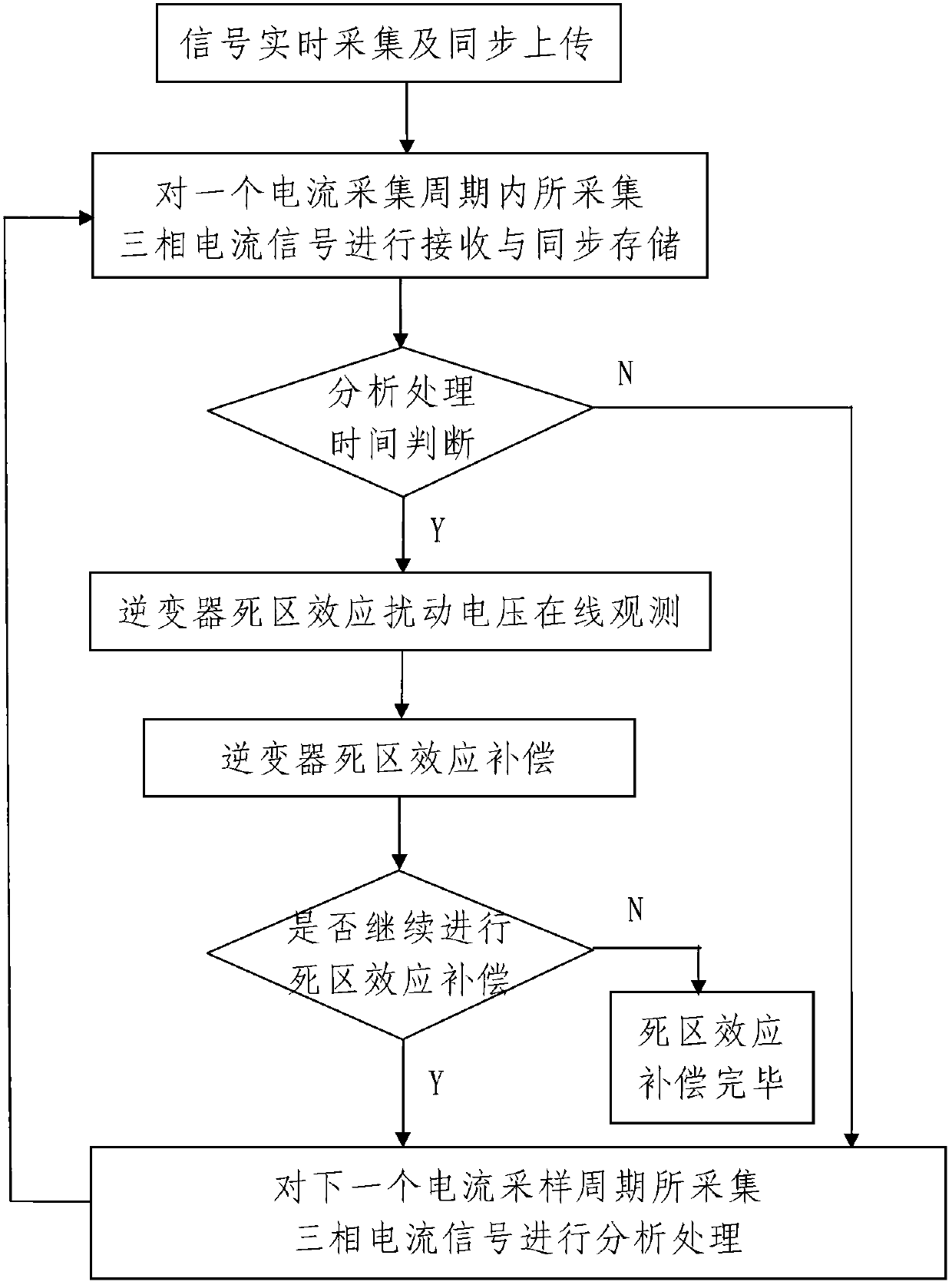
[0056] Such as figure 1 A method for compensating the dead zone effect of a permanent magnet synchronous motor inverter includes the following steps:

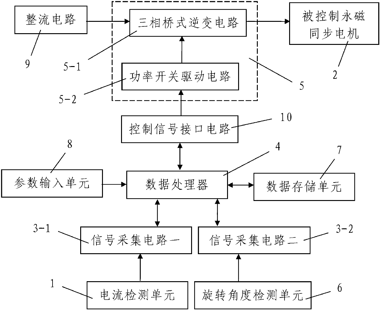
[0057] Step 1. Real-time signal collection and synchronous upload: during the operation of the controlled permanent magnet synchronous motor 2 driven by the inverter 5, the ABC three-phase current of the controlled permanent magnet synchronous motor 2 is respectively monitored in real time by the current detection unit 1 detection, and through the signal acquisition circuit 3-1 and according to the preset current sampling frequency f 1 The real-time detection signal of the current detection unit 1 is synchronously collected, and the three-phase current signal detected in each current collection cycle is synchronously uploaded to the data processor 4; at the same time, the controlled permanent magnet is synchronized through the rotation angle detection unit 6 The rotor rotation electrical angle of the motor 2 is detected in rea...


PUM


Abstract

The invention discloses a method and system for compensating dead zone effects of an inverter of a permanent magnet synchronous motor. The method comprises the steps of real-time collection and synchronous uploading of signals; and on-line compensation of the dead zone effects of the inverter. As for any current sampling period, an analysis and processing process comprises the following steps of collected signal receiving and synchronous saving, analysis and processing time judgment, on-line observation of disturbance voltage of the dead zone effects of the inverter and the compensation of the dead zone effects of the inverter. The system comprises a data processor, a current detection unit, a first signal acquisition circuit, a rotation angle detection unit, a second signal acquisition circuit, a data storage unit and a parameter input unit, wherein the data storage unit and the parameter input unit are respectively connected with the data processor. The method and system is reasonable in design, simple in compensation method and step, convenient to achieve, low in input cost, good in compensation effects and capable of effectively solving the problem that the existing method for compensating dead zone effects of the inverter of the permanent magnet synchronous motor (PMSM) is big in input cost, complex in compensation step, poor in compensation effects and the like.

Description

technical field [0001] The invention belongs to the technical field of PMSM inverter dead zone effect compensation, and in particular relates to a permanent magnet synchronous motor inverter dead zone effect compensation method and system. Background technique [0002] In the PMSM speed control system based on voltage space vector (SVPWM, that is, voltage space vector pulse modulation technology) control, the two switch tubes on the same bridge arm of the inverter (specifically, the three-phase inverter bridge) must be turned on alternately to It meets the working requirements, but due to the non-linear characteristics of the inverter, the two switching tubes of the same bridge arm will cause a straight-through phenomenon instantaneously. Therefore, in order to prevent the direct short-circuit phenomenon of the inverter bridge arm, a fixed switching delay time must be inserted between the control signals of the upper and lower switching tubes of the same bridge arm. However,...

Claims


Application Information

Patent Timeline
IPC IPC(8): H02P21/00H02P21/16
Inventor 肖海峰祁树胜肖军汪春华柯善文薛荣辉康雪娟毕杨刘舟洲毛惠丰孙进博
Owner XIAN AERONAUTICAL UNIV
Why Eureka
Try Eureka