Thermal storage device and air conditioner provided with thermal storage device

A heat storage device and heat storage tank technology, applied in heat storage equipment, compressors with reversible cycles, lighting and heating equipment, etc., can solve the problems of inability to accumulate and achieve the effect of increasing the contact area

Active Publication Date: 2013-06-05
PANASONIC CORP
View PDF4 Cites 2 Cited by
  • Summary
  • Abstract
  • Description
  • Claims
  • Application Information

AI Technical Summary

Problems solved by technology

There is an air layer functioning as a heat insulating material in such a gap, and there is a problem that heat from the compressor 102 cannot be efficiently stored in the heat storage material 103.

Method used


Image

  • Thermal storage device and air conditioner provided with thermal storage device
  • Thermal storage device and air conditioner provided with thermal storage device
  • Thermal storage device and air conditioner provided with thermal storage device

Examples


Embodiment approach 1

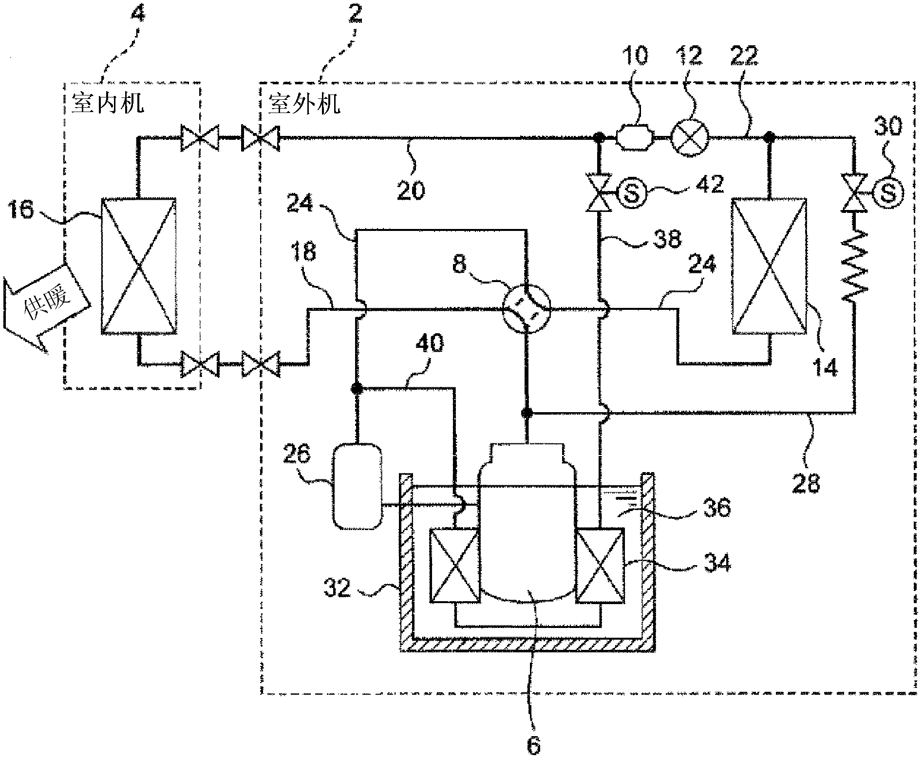
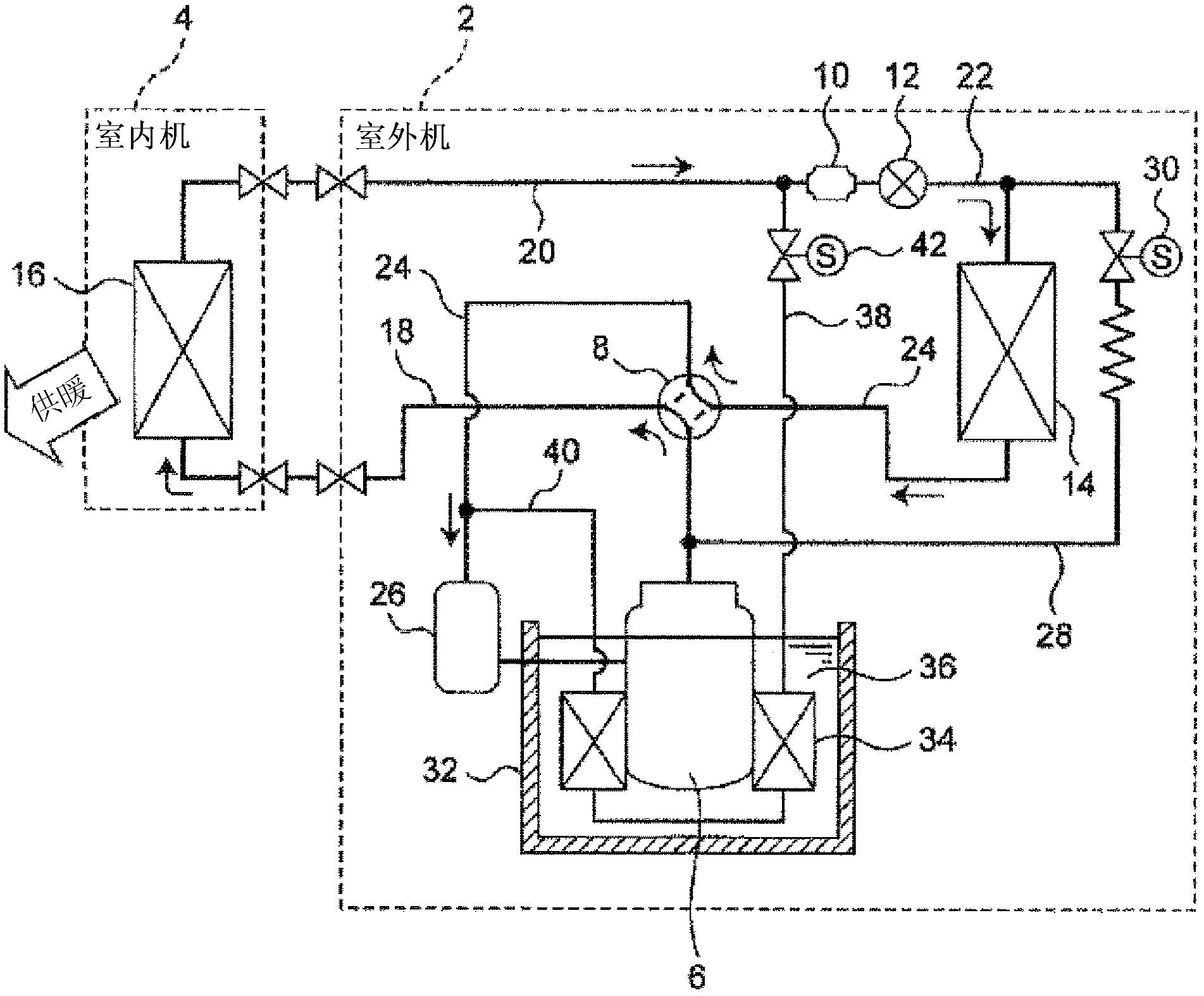
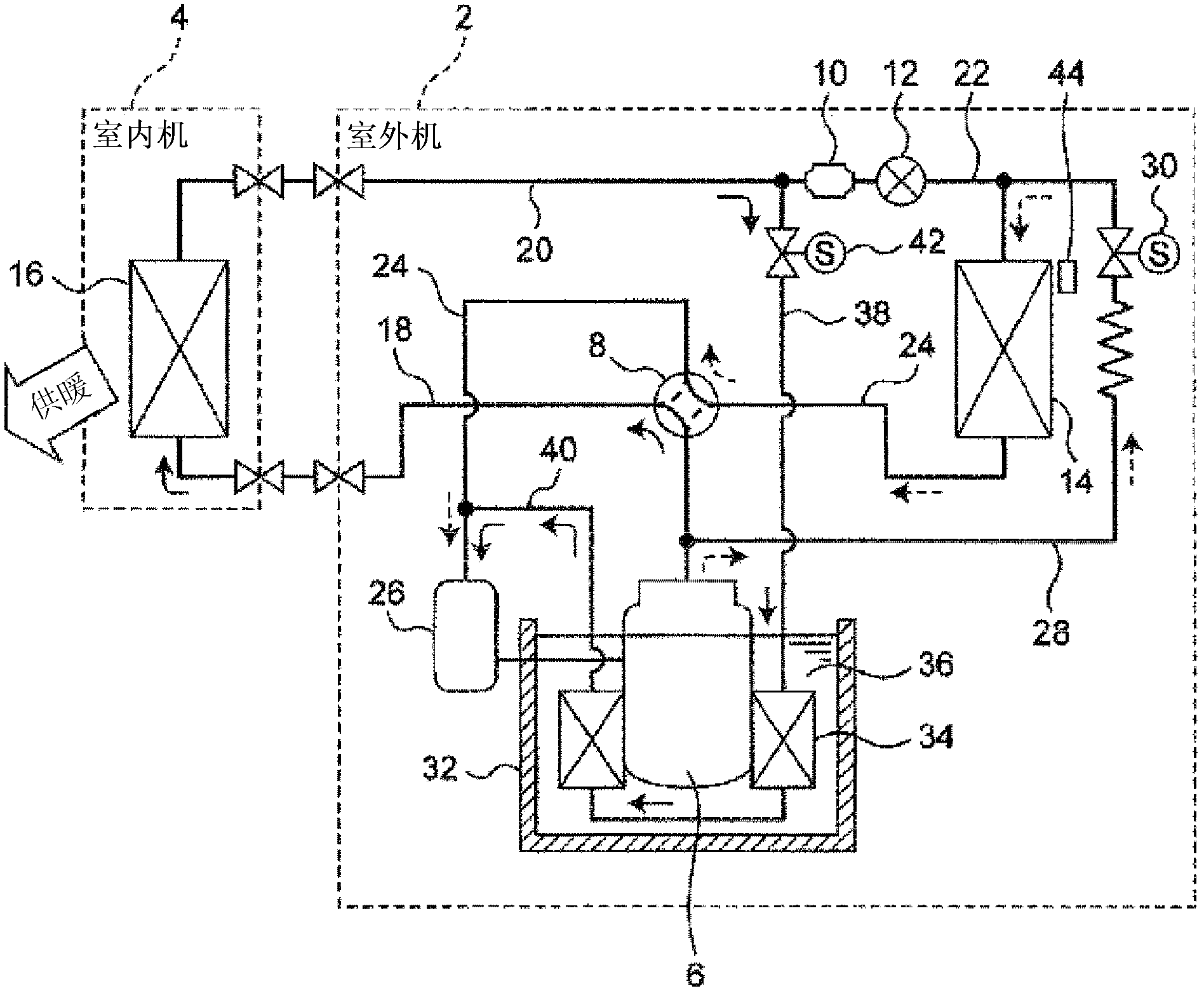
[0031] figure 1 The structure of the air conditioner provided with the heat storage device concerning embodiment of this invention is shown, and an air conditioner is provided with the outdoor unit 2 and the indoor unit 4 mutually connected by refrigerant|coolant piping.

[0032] Such as figure 1 As shown, a compressor 6, a four-way valve 8, a filter 10, an expansion valve 12, and an outdoor heat exchanger 14 are arranged inside the outdoor unit 2, and an indoor heat exchanger 16 is arranged inside the indoor unit 4, which pass through The refrigerant pipes are connected to each other to constitute a refrigeration cycle.

[0033] More specifically, the compressor 6 and the indoor heat exchanger 16 are connected via a first pipe 18 provided with a four-way valve 8 , and the indoor heat exchanger 16 and the expansion valve 12 are connected via a second pipe 20 provided with a filter 10 . In addition, the expansion valve 12 and the outdoor heat exchanger 14 are connected via ...


PUM


Abstract

A thermal storage device, which is arranged so as to surround a compressor (6), and which is for storing heat generated by the compressor (6), is provided with: a thermal storage tank (32) which accommodates a heat storage material (36) for storing the heat generated by the compressor (6); and an adhesive member (52) which has a hardness of not more than 50 on the Asker-C hardness scale, has a thermal conductivity of at least 0.43W/mK, has a thickness of 1-5mm, is arranged in a position facing the compressor (6), and which is for adhering to the compressor (6). The thermal storage tank (32) and the compressor (6) are adhered and fixed so as to be pressed together by a band or a screw, and thus the size of an air layer forming an insulator is reduced, and the heat generated by the compressor (6) can be efficiently transferred to the heat storage material and stored.

Description

technical field [0001] The present invention relates to a heat storage device disposed so as to surround a compressor and accommodate a heat storage material that stores heat generated by the compressor, and an air conditioner including the heat storage device. Background technique [0002] Conventionally, when the outdoor heat exchanger is frosted during the heating operation of the heat pump air conditioner, the four-way valve is switched from the heating cycle to the cooling cycle to perform defrosting. In this defrosting method, although the indoor fan is stopped, there is a disadvantage in that the feeling of heating is lost because cold air is gradually released from the indoor unit. [0003] Therefore, a technique has been proposed in which a heat storage device is installed in a compressor installed in an outdoor unit, and defrosting is performed using waste heat of the compressor stored in the heat storage tank during heating operation (for example, refer to Patent ...

Claims


Application Information

Patent Timeline
Patent Type & Authority Applications(China)
IPC IPC(8): F25B1/00
CPCF25B29/003F25B13/00F25B2400/24Y02E60/14F25B1/00F28D20/00
Inventor 杉尾孝栗须谷广治今坂俊之久保次雄山本宪昭
Owner PANASONIC CORP
Why Eureka
Try Eureka