
Electroencephalograph for determining contact status between electrode and scalp and method for determining same

A contact state, electroencephalogram technology, applied in the field of medical instruments, can solve the problems of inaccurate impedance information, large phase error between resistance and signal wave, decay, etc., and achieves strong circuit anti-interference, improved accuracy, and simple circuit. Effect

Active Publication Date: 2013-06-12
CONTEC MEDICAL SYST
View PDF8 Cites 29 Cited by
  • Summary
  • Abstract
  • Description
  • Claims
  • Application Information

AI Technical Summary

Problems solved by technology

The EEG signal is a low-frequency signal of 0-30Hz. The traditional EEG amplifier circuit is designed for low-frequency signals, and the decay of high-frequency signals that modulate impedance information will be serious, so that the obtained impedance information is not accurate enough.
The Chinese patent with the publication number CN101199418 discloses a "Electroelectric Impedance Detection Circuit and EEG Detection Device". In the patent, an EEG impedance detection circuit is proposed. The circuit forms a loop through a constant current source, a scalp, and a grounding resistance. , the circuit separately sets a grounding resistor for measuring the scalp impedance. The excitation circuit and the test circuit share the same ground. In use, the electrode required as the grounding resistor must be in good contact with the scalp, and the response is not between the real measuring electrode and the reference electrode. Impedance of the EEG model increases the complexity and inaccuracy of the test
[0005] Both of the above two public documents use the traditional sinusoidal AC constant current source as the excitation source for human body bioimpedance measurement. Both the EEG signal and the EEG signal will be input into the EEG signal detection circuit at the same time. The sine wave signal is easy to interfere with the measurement of the computer signal, and the processing circuit is more complicated than other circuits.
However, the measured resistance and signal wave phase error of the sinusoidal AC constant current excitation signal lower than 50KHz is large. When the EEG signal is required to be synchronized with the scalp impedance signal within the specified time, an error will occur. In practical applications, only The three states of good, bad and shedding of the electrode and the scalp are judged, rather than precise resistance value, so the circuit of the sinusoidal AC constant current source used as the excitation source of the human body bio-impedance measurement is too complicated

Method used


Image

  • Electroencephalograph for determining contact status between electrode and scalp and method for determining same
  • Electroencephalograph for determining contact status between electrode and scalp and method for determining same
  • Electroencephalograph for determining contact status between electrode and scalp and method for determining same

Examples


Embodiment 1

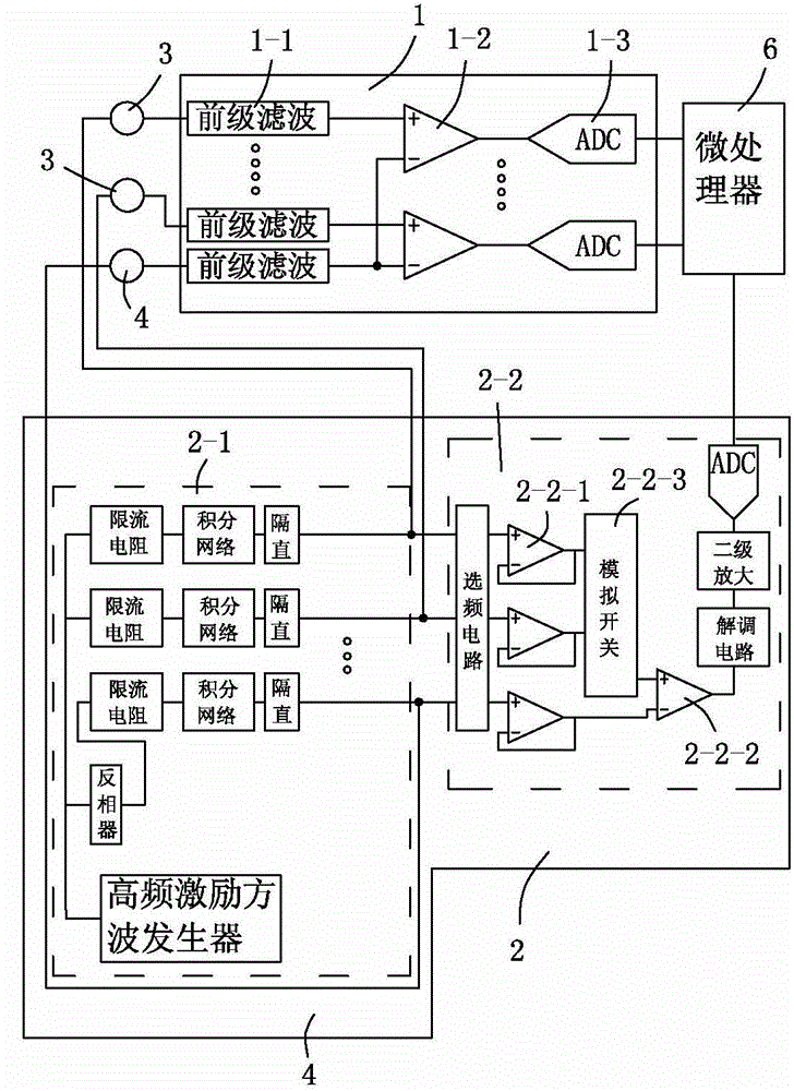
[0027] An embodiment of an electroencephalograph with impedance detection function: see figure 1, the electroencephalograph includes an EEG signal detection circuit 1 and a scalp impedance detection circuit 2, and the EEG signal detection circuit is provided with at least one group of electrodes 3 to be tested and a reference electrode connected to a plurality of contact scalps through lead wires. The EEG signal interface of the electrode 4 can be set in two to three or more groups according to actual needs, and the present embodiment is two groups; wherein, the scalp impedance detection circuit is independent of the EEG signal detection circuit and the electrode interface under test and The reference electrode interface is connected, that is, the analog ground of the scalp impedance detection circuit is separated from the analog ground of the EEG signal detection circuit, and the scalp impedance signal input end of the scalp impedance detection circuit is connected to the meas...

Embodiment 2

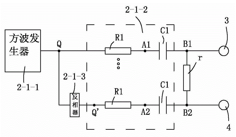
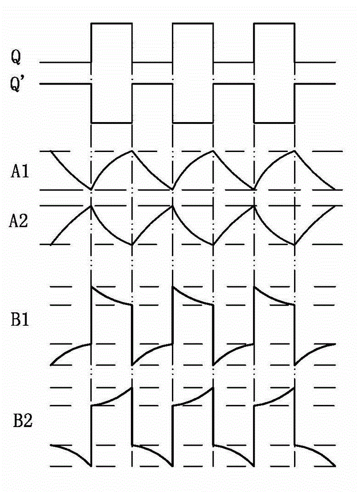
[0040] Embodiment 1 of an electrode contact state judgment method for an electroencephalograph that judges the contact state between electrodes and the scalp based on Example 1: includes an EEG signal detection circuit and a scalp impedance detection circuit, and at least one set of interfaces of the EEG signal detection circuit passes through The lead wire connects a plurality of measured electrodes contacting the scalp and a reference electrode; the scalp impedance detection circuit includes a high-frequency excitation circuit and a scalp impedance acquisition circuit; the high-frequency excitation circuit includes a 60KHz with a duty ratio of 1:1 to a 70KHz square wave generator and a multi-channel resistance-capacitance charging and discharging circuit, the resistance-capacitance charging and discharging circuit is composed of a first resistor and a first capacitor in series, and the output of the square wave generator is connected to an inverter, and the inverter The o...


PUM


Abstract

The invention relates to an electroencephalograph for determining the contact status between an electrode and a scalp and a method for determining the contact status between the electrode and the scalp. The electroencephalograph comprises an electroencephalogram signal detecting circuit and a scalp impedance detecting circuit, wherein the electroencephalogram signal detecting circuit is provided with at least one set of interfaces connected with a reference electrode and a plurality of electrodes to be detected, which are contacted with scalp, through lead wires; and the scalp impedance detecting circuit is independent from the electroencephalogram signal detecting circuit to be connected with the interfaces of the electrodes to be detected and the reference electrode. According to the invention, the electroencephalogram signal detecting circuit and the scalp impedance detecting circuit are respectively detected, the contact status is determined by a threshold value determining method, and the method is simple in circuit, high in circuit anti-interference performance and quick in speed; not only can the detection precision of the scalp impedance be improved, but also the acquiring and the process of the electroencephalogram signal can not be influenced; and the large information content electroencephalogram signal can be most accurately processed, and the scalp impedance information can be most timely processed, so that a product is better in performance.

Description

technical field [0001] The invention belongs to the field of medical instruments, in particular to an electroencephalograph for judging the contact state between an electrode and a scalp and a judging method thereof. Background technique [0002] With the advancement and development of science and technology and the continuous improvement of people's living standards, the requirements for medical testing levels are also getting higher and higher. As an important medical device for detecting brain diseases, the EEG system plays an important role in clinical diagnosis. However, the current EEG products have a small storage capacity, a small number of acquisition leads, poor anti-interference ability, and poor stability. Some EEG detection equipment does not have the function of detecting the connection of electrodes. Electricity and the impedance between the electrodes and the scalp. As the study of brain function by biological cybernetics has become an important aspect of b...

Claims


Application Information

Patent Timeline
IPC IPC(8): A61B5/0478A61B5/053
Inventor 胡坤高瑞斌刘晨亮常衍春吴新亮孙丽花
Owner CONTEC MEDICAL SYST
Learn More