Compound airflow generator, circulating fluidized bed tower-front two-phase premixing device and method

A circulating fluidized bed and composite air flow technology, applied in the field of flue gas purification, can solve the problem of unimproved mixing and uniform distribution of material particles and flue gas, uneven mixing and distribution of flue gas and material particles, and increase of material particles. concentration, etc.

Active Publication Date: 2013-06-12
FUJIAN LONGKING DSDN ENGINEERING CO LTD +1
View PDF7 Cites 15 Cited by
  • Summary
  • Abstract
  • Description
  • Claims
  • Application Information

AI Technical Summary

Problems solved by technology

Although the device increases the residence time of the material particles and the flue gas in this area, it does not improve the mixing and homogenization distribution of the material particles and the flue gas. The

Method used


Image

  • Compound airflow generator, circulating fluidized bed tower-front two-phase premixing device and method
  • Compound airflow generator, circulating fluidized bed tower-front two-phase premixing device and method
  • Compound airflow generator, circulating fluidized bed tower-front two-phase premixing device and method

Examples


Embodiment 1

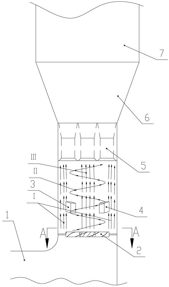
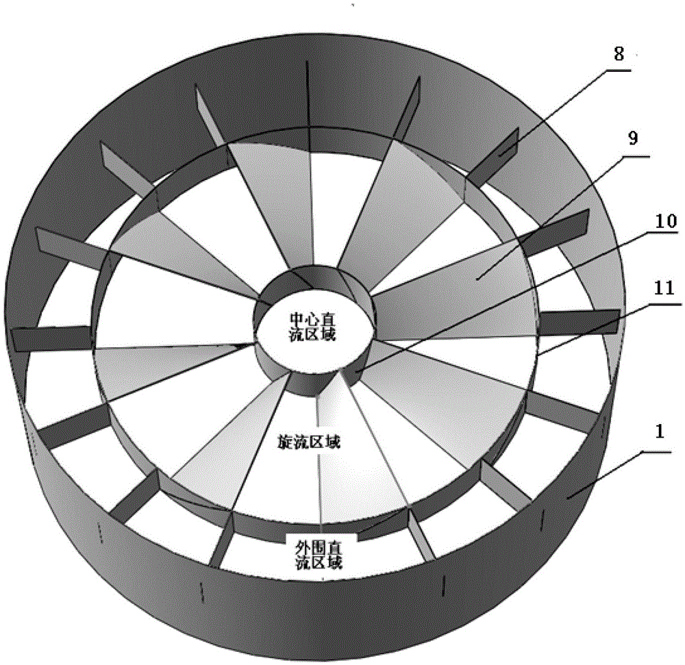
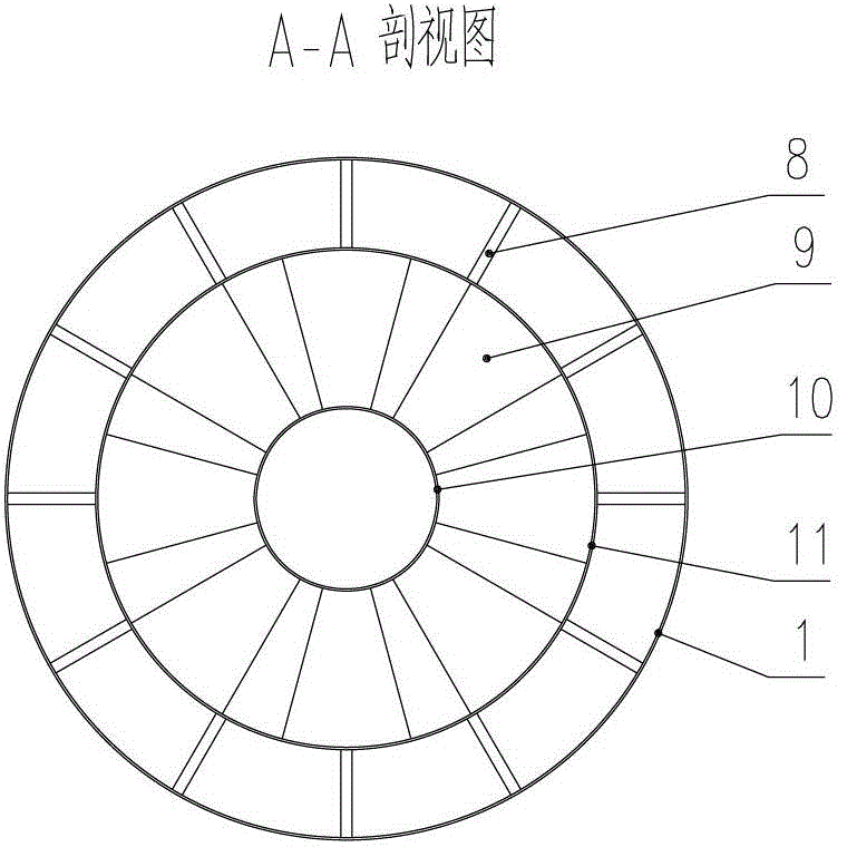
[0067] according to figure 1 As shown in the schematic diagram of the structure, the composite air flow generator is assembled. The cross-sectional area of ​​the inner sleeve accounts for 12% of the cross-sectional area of ​​the flue, and the cross-sectional area between the inner sleeve and the outer sleeve accounts for 58% of the cross-sectional area of ​​the flue. The cross-sectional area between the outer sleeve and the inner wall of the flue accounts for 30% of the cross-sectional area of ​​the flue; 15 swirl vanes are set between the inner sleeve and the outer sleeve, and each swirl guide vane is connected with the flue The included angle of the central axis is 45°; so that the flow rate of the direct air flow in the central area of ​​the flow field is 15% of the total smoke flow; the flow rate of the direct air flow in the peripheral wall area is 35% of the total smoke flow; The flow rate is 50% of the total flue gas flow; the angle between the velocity direction of the...

Embodiment 2

[0073] Assemble the composite air flow generator according to the technical scheme of embodiment 1, the difference is that the cross-sectional area of ​​the inner sleeve accounts for 5% of the cross-sectional area of ​​the flue in this embodiment; the cross-sectional area between the inner sleeve and the outer sleeve The area accounts for 50% of the cross-sectional area of ​​the flue; the cross-sectional area between the outer sleeve and the inner wall of the flue accounts for 45% of the cross-sectional area of ​​the flue; 6 swirl blades are set between the inner sleeve and the outer sleeve , the angle between each swirl guide vane and the central axis of the flue is 30°; so that the flow rate of the direct current flow in the central area of ​​the flow field is 7% of the total smoke flow; 50%; the swirling air flow between the two is 43% of the total flue gas flow; the angle between the speed direction of the swirling air flow and the direction of the flue gas flow is 30°;

...

Embodiment 3

[0078] Assemble the composite air flow generator according to the technical scheme of Example 1. The difference is that the cross-sectional area of ​​the inner sleeve in this embodiment accounts for 10% of the cross-sectional area of ​​the flue, and the cross-sectional area between the inner sleeve and the outer sleeve The area accounts for 51% of the cross-sectional area of ​​the flue, and the cross-sectional area between the outer sleeve and the inner wall of the flue accounts for 39% of the cross-sectional area of ​​the flue; 10 swirls are evenly arranged between the inner sleeve and the outer sleeve Blades, the angle between each swirl guide vane and the central axis of the flue is 40°; so that the direct current flow in the central area of ​​the flow field is 12% of the total flue gas flow; the direct current flow in the peripheral wall area is the total flue gas flow 43% of the swirling airflow between the two is 45% of the total flue gas flow; the angle between the veloc...


PUM


Abstract

The invention provides a compound airflow generator which comprises a plurality of fixing plate supports, a plurality of rotational flow guide vanes, an inner sleeve and an outer sleeve, wherein two ends of each rotational flow guide vane are respectively arranged on the external wall of the inner sleeve and the inner wall of the outer sleeve, the included angle between the plane of each rotational flow guide vane and the horizontal plane is 30-70 degree, the fixing plate supports are used for fixing the structure formed by the outer sleeve, the inner sleeve and the rotational flow guide vanes, one end of each fixing plate support is arranged on the external wall of the outer sleeve, the other end of the fixing plate support is arranged on the inner wall of a tower front flue, and the fixing plate support is vertically arranged. After passing by the compound airflow generator, smoke forms a direct current airflow in the inner sleeve, forms rotational flow between the inner sleeve and the outer sleeve, and forms a direct current airflow outside the outer sleeve, thus forming a direct-rotational-direct airflow flow field, under the disturbance of the direct-rotational-direct airflow flow field, particle granules and the smoke are premixed and homogenized, so that the smoke thoroughly reacts in a purification tower, and the purification efficiency of the smoke is improved.

Description

technical field [0001] The invention relates to the technical field of flue gas purification, in particular to a composite gas flow generator and a two-phase premixing device and method before a circulating fluidized bed tower. Background technique [0002] SO contained in boiler flue gas 2 , SO 3 , HCl, HF, NOx, heavy metals, PM2.5, dioxin and other multi-component pollutants. In order to purify the flue gas and remove the toxic substances in the existing technology, the flue gas drying of the circulating fluidized bed is often used. Multi-pollutant synergistic purification process, this process is a rapid removal of SO from flue gas by using the intense turbulence and efficient heat and mass transfer in the fluidized bed 2 , SO 3 , HCl, HF, NOx, heavy metals, PM2.5, dioxin and other multi-component pollutant technologies. The circulating fluidized bed flue gas dry multi-pollutant synergistic purification process has the advantages of large amount of flue gas treatment,...

Claims


Application Information

Patent Timeline
IPC IPC(8): B01D53/83B01J8/24
Inventor 赖毅强郭厚焜张忠平饶益龙
Owner FUJIAN LONGKING DSDN ENGINEERING CO LTD
Why Eureka
Try Eureka