
One-gun multi-beam welding control device and method of electron beam welding machine

A technology of electron beam welding and control device, which is applied in the direction of electron beam welding equipment, welding equipment, manufacturing tools, etc., and can solve the problems of unfavorable welding of precision workpieces, etc.

Active Publication Date: 2014-12-31
GUILIN THD TECH CO LTD
View PDF6 Cites 2 Cited by
  • Summary
  • Abstract
  • Description
  • Claims
  • Application Information

AI Technical Summary

Problems solved by technology

[0004] At present, the electron beam one gun multi-beam welding technology is fast moving between different positions, and the electron beam is continuously beamed, leaving a scanning trace during it, which is not good for the welding of precision workpieces, and it is necessary to improve it.

Method used


Image

  • One-gun multi-beam welding control device and method of electron beam welding machine
  • One-gun multi-beam welding control device and method of electron beam welding machine
  • One-gun multi-beam welding control device and method of electron beam welding machine

Examples


Embodiment 1

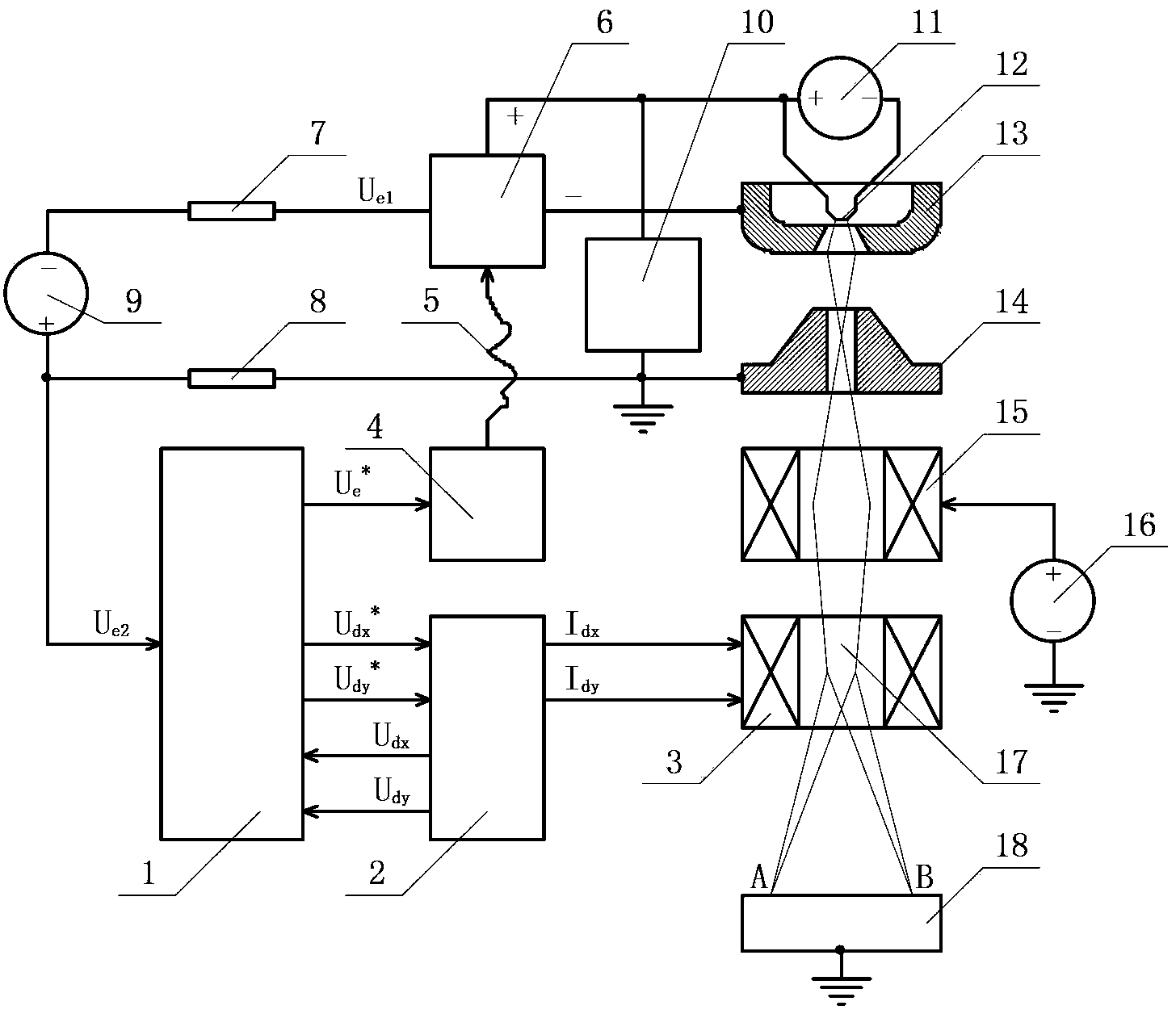
[0056] An electron beam welding machine one gun multi-beam welding control device such as figure 1As shown, it is mainly composed of a central controller 1, a bias scan drive power supply 2, a bias scan winding 3, an optical fiber drive power supply 4, an optical fiber 5, an electron beam current control unit 6, a first electron beam current sampling resistor 7 and a second electron beam Composed of flow sampling resistor 8. The above-mentioned control device is used to control the electron gun, so that the electron beam 17 emitted by the electron gun can move quickly between different positions of the workpiece 18 , and no unnecessary scanning marks will be left on the workpiece 18 during the movement of the electron beam. The selected electron gun is an electron gun known in the prior art. In the present embodiment, the electron gun system includes a cathode 12, a focusing pole 13, an anode 14, a focusing winding 15, an acceleration power supply 9, an acceleration voltage sa...

Embodiment 2

[0080] Embodiment 2 is substantially the same as Embodiment 1, except that the electron beam current control unit 6 adopts Figure 5 Another structure shown, which with the Figure 4 The difference is that the former electron beam directly adjusts the electron tube T8 through the grid bias voltage, so the wiring of the electron tube T8 is also different. Figure 5 The secondary winding of the medium and high voltage isolation transformer B1 lacks the fifth winding, and the corresponding fourth rectifying and filtering circuit ZL4 does not exist, and the grid bias cut-off voltage is generated by dividing the voltage from the accelerating power supply 9 by the resistor R30 connected in series with the accelerating voltage sampling circuit 10 . The anode of T8 is connected to the cathode 12 of the electron gun, the high voltage end of the accelerating voltage sampling circuit 10 and one end of R30, and the other end of R30 is connected to one end of the filament of T8, one end o...


PUM


Abstract

The invention discloses a one-gun multi-beam welding control device and method of an electron beam welding machine. The device mainly comprises a central control unit, a deflection scanning driving power supply, a deflection scanning winding, an optical fiber driving power supply, optical fibers, an electron beam flow control unit, a first electron beam flow sampling resistor and a second electron beam flow sampling resistor. The one-gun multi-beam welding control device and method of the electron beam welding machine have the advantages that electron beam flow closed-loop control can be realized at a high-voltage end and the adjusting speed is fast; by using the optical fibers for transmitting signals, high-voltage insulation isolation is realized; by using two loops of analog optical fibers and transmitting signals through a differential mode, common-mode interference caused by change of transceiver device performance is eliminated; an electron beam flow is simultaneously sampled at a high-voltage end and a low-voltage end, and the nonlinearity of an electron beam flow control system and the drift of the working point of the electron beam flow control system are corrected by the central control unit; and excessive scanning traces left by electron beams when the electron beams move among different points in the one-gun multi-beam welding process are eliminated.

Description

technical field [0001] The invention relates to electron beam welding equipment, in particular to an electron beam welding machine one gun multi-beam welding control device and a method thereof. Background technique [0002] Electron beam welding is a process of local rapid heating to high temperature followed by rapid cooling. With the movement of the heat source, the temperature of the entire workpiece changes sharply with time and space, and the thermophysical properties of the material also change sharply with temperature, and there are also latent heat phenomena during melting and phase transition. In electron beam welding production, welding residual stress and deformation are inevitable. Welding residual stress and deformation may not only cause defects such as hot cracks, cold cracks, and brittle fractures, but also affect the bearing capacity of the structure under certain conditions, such as strength, stiffness, and compression stability. In addition, it will also...

Claims


Application Information

Patent Timeline
IPC IPC(8): B23K15/02
Inventor 黄小东韦寿祺陆思恒郭华艳王伟蒋思远陆苇黄海黄地送
Owner GUILIN THD TECH CO LTD
Learn More