
Multi-functional continuous magneto-controlled sputter coating device

A magnetron sputtering coating, multi-functional technology, applied in the direction of sputtering coating, ion implantation coating, vacuum evaporation coating, etc., can solve the problems of low production efficiency, waste of energy, difficult installation and processing, etc., to prevent Ineffective area, improved versatility, and the effect of avoiding pinch marks

Active Publication Date: 2015-04-22
GUANGDONG ZHICHENG CHAMPION GROUP
View PDF4 Cites 0 Cited by
  • Summary
  • Abstract
  • Description
  • Claims
  • Application Information

AI Technical Summary

Problems solved by technology

However, this coating method has the following defects: a. When vertical equipment is used, it is difficult to fix and clamp the coating substrate. Fixing with a clamp will leave a clamp mark at the fixed position, resulting in an invalid area on the edge, and the coating process is difficult to control. At the same time, it is not convenient to coat substrates of various sizes and specifications; b. This coating method uses the same end to enter and exit the coating chamber for coating. This kind of coating auxiliary takes a long time, the production efficiency is not high, and energy is wasted
However, its main problem is that dirt such as particles falling from the cavity will fall on the substrate, and it can only be used in fields that do not require high cleanliness of the substrate.
[0008] 3. Inclined type: Inclined equipment is placed obliquely at a certain angle with the horizontal plane. The coating substrate passes through the equipment obliquely, and the coating process is also obliquely erected. For the inclined equipment, the advantages of the two equipments are combined, but due to The equipment is inclined as a whole, and its installation and processing are difficult

Method used


Image

  • Multi-functional continuous magneto-controlled sputter coating device
  • Multi-functional continuous magneto-controlled sputter coating device
  • Multi-functional continuous magneto-controlled sputter coating device

Examples


Embodiment Construction

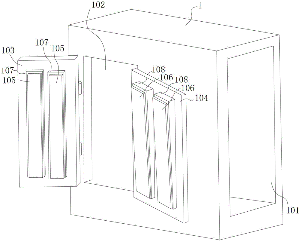
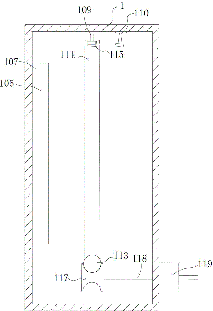
[0038] Such as figure 1 As shown, the multifunctional continuous magnetron sputtering coating device described in this embodiment includes a film feeding chamber 2, a first transition chamber 3, a first coating buffer chamber 4, a coating chamber 1, and a second coating chamber arranged in sequence. The buffer chamber 5, the second transition chamber 6, and the film output chamber 7, the feeding station 9 is set on the side of the film feeding chamber 2 away from the first transition chamber 3, and the film output chamber 7 is far away from the side of the second transition chamber 6 The unloading station 10 is set, the isolation valve 8 is set between the film feeding chamber 2 and the first transition chamber 3, the isolation valve 8 is set between the first transition chamber 3 and the first coating buffer chamber 4, and the second coating buffer chamber 5 and An isolation valve 8 is arranged between the second transition chamber 6, an isolation valve 8 is arranged between ...


PUM


Abstract

Disclosed is a multi-functional continuous magneto-controlled sputter coating device which comprises at least one coating chamber. Vertical splashboards and inclined splashboards are installed on the inner wall of the coating chamber and can be alternatively used for magneto-controlled sputter coating, a moveable vertical base material bearing frame is installed inside the coating chamber corresponding to the vertical splashboards, and a moveable inclined base material bearing frame is installed inside the coating chamber corresponding to the inclined splashboards. The vertical splashboards and the inclined splashboards which can be used alternatively are installed at a splashboard position port of the coating chamber, and the vertical base material bearing frame and the inclined base material bearing frame are installed correspondingly, so that different splashboard materials can be selected for coating of coating base materials to meet different requirements; and the vertical splashboards and the inclined splashboards can be used alternatively, so that the coating chamber can be suitable for coating of more standards of products, and the generality of the coating device is improved.

Description

technical field [0001] The invention relates to the technical field of magnetron sputtering coating, in particular to a multifunctional continuous magnetron sputtering coating device. Background technique [0002] Magnetron sputtering coating technology is a widely used vacuum coating technology method at present. It is widely used in optics, microelectronics, wear resistance, corrosion resistance, decoration and other industrial fields to provide reliable and stable thin film coatings, which can be used for coating A product provides certain aspects of specific performance. For example, coating a layer of ITO film on the surface of glass can form transparent conductive glass for the production of LCD displays, touch screens, etc. [0003] The magnetron sputtering technology mainly uses the electric field on the sputtering target to excite the plasma in a rare gas state, and under the combined control of the magnetic field and the electric field, the positive ions bombard t...

Claims


Application Information

Patent Timeline
Patent Type & Authority Patents(China)
IPC IPC(8): C23C14/35C23C14/56
CPCC23C14/566H01J37/3464H01J37/3429C23C14/35H01J37/3417C23C14/50H01J37/3435
Inventor 陈宇
Owner GUANGDONG ZHICHENG CHAMPION GROUP
Learn More