Gas-liquid one-way mixing device for urea pump

A technology of mixing device and urea pump, applied in the field of urea pump, can solve problems such as one-way mixing of gas and liquid, and achieve the effect of ensuring normal operation

Active Publication Date: 2013-06-12
KAILONG HIGH TECH
View PDF6 Cites 3 Cited by
  • Summary
  • Abstract
  • Description
  • Claims
  • Application Information

AI Technical Summary

Problems solved by technology

[0004] The object of the present invention is to provide a gas-liquid one-way mixing device for urea pumps, which can effectively avoid the crystallization of urea solution around the mixing chamber, the inlet and outlet of the mixing chamber, and the nozzle, and ensure the normal operation of the SCR post-treatment system to solve the problem of Problems existing in the urea pump gas-liquid one-way mixing in the prior art

Method used


Image

  • Gas-liquid one-way mixing device for urea pump
  • Gas-liquid one-way mixing device for urea pump

Examples


Embodiment 1

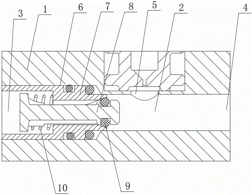
[0017] see figure 1 as shown, figure 1 It is a schematic structural diagram of a gas-liquid one-way mixing device for a urea pump provided in Embodiment 1 of the present invention.

[0018] In this embodiment, a gas-liquid one-way mixing device for a urea pump includes a housing 1, and a mixing chamber 2 is opened in the housing 1, one end of the mixing chamber 2 is a gas inlet 3, and the other end is a The mixed liquid outlet 4, and the housing 1 is provided with a urea solution inlet 5 at a position corresponding to the mixing chamber 2, and the urea solution inlet 5 adopts a structure that enters the mixing chamber 2 vertically, and the structure makes the degree of gas-liquid mixing Preferably, one end of the gas inlet 3 on the mixing chamber 2 is provided with a one-way valve 6 that is sealed with the inner wall of the housing 1. The one-way valve 6 includes a valve seat 7 and a piston 8, and the piston 8 passes through a " The O"-shaped sealing ring 9 is in sealing con...

Embodiment 2

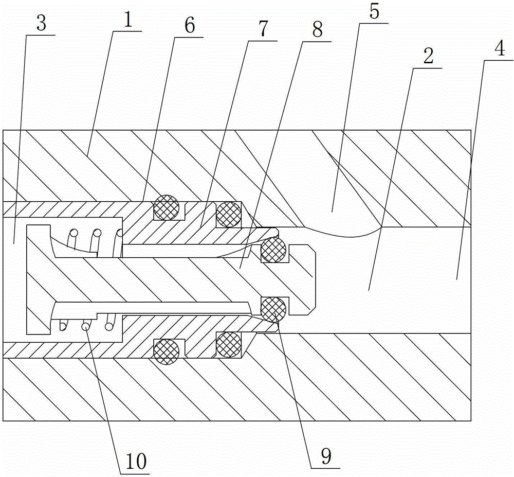
[0020] see figure 2 as shown, figure 2 It is a schematic structural diagram of a gas-liquid one-way mixing device for a urea pump provided in Embodiment 2 of the present invention.

[0021] In this embodiment, the difference from Embodiment 1 lies in the angle at which the urea solution inlet 5 enters the mixing chamber 2. In this example, the structure of entering the mixing chamber 2 obliquely downward is adopted, and this structure makes it easier to discharge gas and liquid after mixing in the mixing chamber 2. smooth.

[0022] When working, when the pressure in the mixing chamber 2 is greater than the pressure at the gas inlet 3 end, the sealing ring of the check valve 6 will seal the piston 8 to prevent the urea mixture from entering the gas circuit. When the internal pressure is high, the piston 8 of the one-way valve 6 opens, and the gas enters the mixing chamber 2 to meet the requirement of mixing with urea, and is discharged from the mixed liquid outlet 4 after m...


PUM


Abstract

The invention discloses a gas-liquid one-way mixing device for a urea pump. The gas-liquid one-way mixing device comprises a shell; a mixing cavity is formed in the shell; one end of the mixing cavity is provided with a gas inlet, and the other end of the mixing cavity is a mixed liquid outlet; the shell is provided with a urea solution inlet corresponding to the mixing cavity; the mixing cavity is provided with a one-way valve which is sealed with the inner wall of the shell, at the end provided with the gas inlet; the one-way valve comprises a valve seat and a piston; the piston is arranged on the valve seat in a sealed way; and the piston reciprocates along the valve seat in the mixing cavity under the action of pressure difference from the gas inlet. The one-way valve is arranged in the mixing cavity of the gas-liquid one-way mixing device for the urea pump, and the piston of the one-way valve moves to reduce and eliminate urea crystallization accumulated in the mixing cavity and to ensure the normal operation of a selective catalytic reduction (SCR) after-treatment system.

Description

technical field [0001] The invention relates to a urea pump, in particular to a gas-liquid one-way mixing device for the urea pump. Background technique [0002] At present, the rapid development of motor vehicles is accompanied by serious air pollution, showing the characteristics of regional complex. The air pollution in many big cities has changed from soot-type pollution to combined soot and motor vehicle pollution, and a few megacities have clearly shown photochemical smog-type (ie, motor vehicle exhaust) air pollution. Therefore, the research on diesel vehicle exhaust emission pollution control technology is extremely important and urgent. [0003] From the perspective of the development of commercial vehicles, diesel engines are their main power. The exhaust after-treatment system for emission control in Stage IV mainly adopts the route of SCR after-treatment system. SCR (Selective Catalyst Reduction) is installed in the exhaust system of diesel vehicles to catalyt...

Claims


Application Information

Patent Timeline
Patent Type & Authority Applications(China)
IPC IPC(8): F01N3/28
Inventor 臧志成
Owner KAILONG HIGH TECH
Why Eureka
Try Eureka