Engine piston mechanism and machining method thereof as well as corresponding engine and automobile

A piston mechanism and engine technology, applied in the direction of engine components, machines/engines, pistons, etc., can solve the problems of complex piston processing technology, piston skirt knocking noise, high manufacturing precision requirements, etc., to achieve stable piston head and reduce quality , The effect of ensuring accuracy

Inactive Publication Date: 2013-06-12
GREAT WALL MOTOR CO LTD
View PDF7 Cites 5 Cited by
  • Summary
  • Abstract
  • Description
  • Claims
  • Application Information

AI Technical Summary

Problems solved by technology

[0005] ③The piston reciprocates linearly for reversing. Since the piston skirt is in rigid contact with the cylinder wall, the piston skirt is prone to cylinder knocking noise;
[0007] In addition, the existing piston processing technology is complex, the manufacturing precision is high, the process is complicated, and the production cost is high

Method used


Image

  • Engine piston mechanism and machining method thereof as well as corresponding engine and automobile
  • Engine piston mechanism and machining method thereof as well as corresponding engine and automobile
  • Engine piston mechanism and machining method thereof as well as corresponding engine and automobile

Examples


Embodiment 1

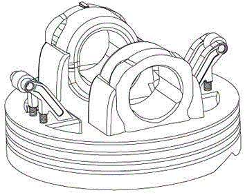
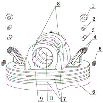
[0040] A kind of engine piston mechanism, structure such as Figure 1 to Figure 3 As shown, it includes a piston head 6, a piston skirt and a piston pin seat 8.

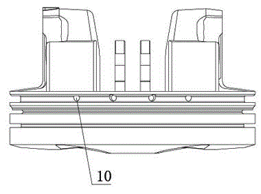
[0041] The piston head 6 is provided with four oil holes 10, and the outer circumference is provided with three piston grooves 7 along the circumference, as image 3 shown.

[0042] The piston pin seat 8 is fixedly connected to the end surface of the piston head 6, and has two axially spaced structures with piston pin holes 11, and the inner wall of the piston pin hole 11 is provided with an oil storage tank 9 in the axial direction. The structure of the piston pin seat 8 reduces the overall mass of the piston, and the light weight of the piston is conducive to reducing the impact force on the piston pin, connecting rod, and crankshaft. In addition, the mass of the piston is small, and the inertial force when the piston reciprocates is small, and the inertia The smaller the force is, the more favorable it is for th...

Embodiment 2

[0047] An engine, the main structure of the engine differs from the prior art only in that its piston mechanism is exactly the same as that of Embodiment 1.

[0048] The structure of other parts of the engine is the same as the prior art.

[0049] When the motor in this embodiment is working:

[0050] The roller 1 is in rolling contact with the cylinder wall. Compared with the traditional piston, the contact area between the roller 1 and the cylinder wall is small, thereby reducing the wear of the piston and improving the service life of the engine.

Embodiment 3

[0052] A kind of automobile, the difference between this automobile and the prior art is that its engine has exactly the same structure as embodiment 2.

[0053] The structure of other parts of this automobile is identical with prior art.


PUM


Abstract

The invention discloses an engine piston mechanism which comprises a piston head, a piston pin seat fixedly connected to the end surface of the piston head, and a piston skirt part arranged at the periphery of the piston pin seat, wherein the piston skirt part comprises two support parts and a roller column; the two support parts are fixedly connected to the end surface of the piston head and are symmetrically arranged at the two sides of the piston pin seat along the axial direction of the piston pin seat; and the roller column is fixedly connected to the support parts and is contacted with the wall of a cylinder in a rolling way when a piston makes reciprocating motion. The invention also discloses a machining method of the engine piston mechanism, and an engine and an automobile which are respectively provided with the engine piston mechanism. According to the engine piston mechanism, the piston skirt part and the wall of the piston are in rolling friction, so that the frictional loss of the piston skirt part and the wall of the cylinder can be reduced, and the fuel economy is improved. The engine piston mechanism is suitable for various automobile engines, and is further applied to various automobiles.

Description

technical field [0001] The invention belongs to the field of automobiles, and relates to an automobile engine, in particular to an engine piston mechanism, a processing method thereof, a corresponding engine and an automobile. Background technique [0002] The piston is the "heart" of the automobile engine, which bears alternating mechanical loads and thermal loads, and is one of the key components in the engine with the worst working conditions. The function of the piston is to withstand the gas pressure and transmit it to the connecting rod through the piston pin to drive the crankshaft to rotate. Because the piston works under the harsh conditions of high temperature, high pressure, high speed and poor lubrication, it is prone to failure. The specific reasons are as follows: [0003] ①Because the connecting rod and the piston are not in a straight line, according to the principle of force decomposition, the huge thrust generated by the gas during combustion and expansion...

Claims


Application Information

Patent Timeline
Patent Type & Authority Applications(China)
IPC IPC(8): F02F3/00
Inventor 常青马瑞瑄高志龙杨红天陈彦如
Owner GREAT WALL MOTOR CO LTD
Why Eureka
Try Eureka