Supercharge Your Innovation With Domain-Expert AI Agents!

Temperature detecting circuit based on thermistor

A technology of temperature detection circuit and thermistor, which is applied to thermometers, thermometers, measuring devices and other directions using electrical/magnetic components directly sensitive to heat, can solve the problems of low capacitance value accuracy, low cost and large temperature drift, etc. Achieve the effect of reducing development cost, simple detection method and high detection accuracy

Inactive Publication Date: 2013-06-12
SHANGHAI SHUANG DIAN ELECTRIC
View PDF5 Cites 9 Cited by
  • Summary
  • Abstract
  • Description
  • Claims
  • Application Information

AI Technical Summary

Problems solved by technology

This detection method is low in cost and easy to develop, but if the capacitance of the capacitor is selected to be small, the frequency of Uout is relatively high and it is difficult to accurately detect the resistance of Rξ
On the contrary, if the capacitance value of the capacitor is large, the accuracy of the capacitance value is low, and the temperature drift is large
Therefore, the detection accuracy of this circuit is low

Method used


Image

  • Temperature detecting circuit based on thermistor
  • Temperature detecting circuit based on thermistor
  • Temperature detecting circuit based on thermistor

Examples


Embodiment Construction

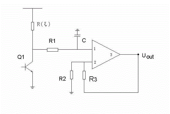
[0013] see image 3 , the specific implementation method adopts the following technical scheme: it includes triode Q1, thermistor Rξ, capacitor C, operational amplifier A, first resistor R1, second resistor R2, third resistor R3, the emitter of the triode Q1 Connected to the ground terminal, the collector of the triode Q1 is respectively connected to the thermistor Rξ and a section of the first resistor R1, the other end of the thermistor R is connected to the power supply, and the other end of the first resistor R1 is respectively connected to the capacitor C and the operational amplifier A The other end of the capacitor C is connected to the ground terminal, the pin 2 of the operational amplifier A is respectively connected to a section of the second resistor R2 and the third resistor R3, and the other end of the third resistor R3 is connected to the ground terminal , the other end of the second resistor R2 is connected to the output end 3 of the operational amplifier A.

...


PUM


Abstract

The invention relates to a temperature detecting circuit based on a thermistor, in particular to the technical field of temperature measurement. The temperature detecting circuit based on the thermistor comprises an audion, the thermistor, a capacitor, an operational amplifier, a first resistor, a second resistor and a third resistor. An emitting electrode of the audion is connected with a grounded end. The thermistor and one end of the first resistor are respectively connected with a collector electrode of the audion. The other end of the thermistor is connected with a power source. The capacitor and a pin of the operational amplifier are respectively connected with the other end of the first resistor. The other end of the capacitor is connected with the grounded end. The pin of the operational amplifier is connected with one end of the second resistor and one end of the third resistor. The other end of the third resistor is connected with the grounded end. The other end of the second resistor is connected with an output end of the operational amplifier. The temperature detecting circuit based on the thermistor is simple in structure, high in detecting accuracy and capable of reducing development cost. A detecting method is enabled to be easy and convenient.

Description

Technical field: [0001] The invention relates to the technical field of temperature detection, in particular to a temperature detection circuit based on a thermistor. Background technique: [0002] The thermistor in the IGBT module needs to accurately detect its resistance value, and the temperature of the thermistor in the IGBT module is determined by looking up the table according to the resistance value. The accurate detection of the thermistor can improve the reliability of the IGBT and prevent the IGBT module from being damaged due to over-temperature. [0003] There are two commonly used thermistor detection circuits: [0004] The first one is to directly use a constant voltage source U1 to supply power through a known resistance resistor R1 and the thermistor Rξ to divide the voltage, and to detect the voltage U2 on the thermistor through A / D. Then the formula Rξ=U2*R1 / (U1-U2) method can be very accurate, but the A / D chip is expensive, and the cost of us...

Claims


Application Information

Patent Timeline
IPC IPC(8): G01K7/22
Inventor 王鸿雁王华东刘金虹
Owner SHANGHAI SHUANG DIAN ELECTRIC
Features
  • R&D
  • Intellectual Property
  • Life Sciences
  • Materials
  • Tech Scout
  • Unparalleled Data Quality
  • Higher Quality Content
  • 60% Fewer Hallucinations
Learn More