High-swing programmable current source

A technology of programming current and high swing, applied in the field of current source, can solve problems such as consumption voltage drop, and achieve the effect of increasing output swing and improving output swing

Active Publication Date: 2014-11-19
HUNAN RONGHE MICROELECTRONICS
View PDF6 Cites 1 Cited by
  • Summary
  • Abstract
  • Description
  • Claims
  • Application Information

AI Technical Summary

Problems solved by technology

Analysis of the reasons: first, the threshold voltage of the high-voltage tube is larger than that of the low-voltage tube, and the saturation voltage drop Vds required by the high-voltage tube is larger when the same current accuracy and yield are satisfied; On the road, the voltage drop to consume

Method used


Image

  • High-swing programmable current source
  • High-swing programmable current source
  • High-swing programmable current source

Examples


Embodiment Construction

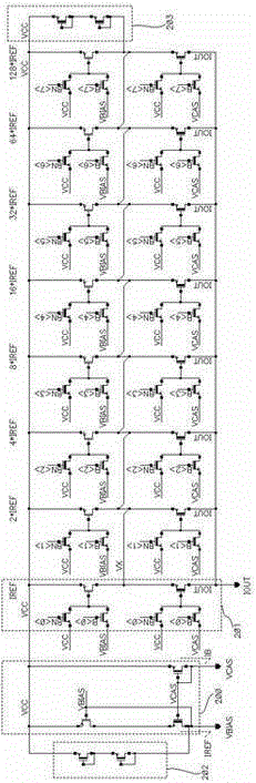
[0017] The present invention is as image 3 , Figure 4 As shown, it includes a reference circuit, a mirror circuit, and a protection circuit.

[0018] The reference circuit 200 is composed of a low-voltage PMOS transistor PM1 and high-voltage PMOS transistors M2 and M3; the source terminal of the high-voltage PMOS transistor M2 is connected to the power supply voltage VCC, and the drain terminal and the gate terminal are connected to the gate terminal of the high-voltage PMOS transistor M3. The terminal bias voltage VCAS, the reference current IB flows through the high-voltage PMOS transistor M2, and the gate terminal bias voltage VCAS is generated; the source terminal of the low-voltage PMOS transistor PM1 is connected to the power supply voltage VCC, and the gate terminal is connected to the drain terminal of the high-voltage PMOS transistor M3. The gate terminal bias voltage VBIAS of the current mirror tube is connected together, and the drain terminal is connected to the...


PUM


Abstract

The invention discloses a high-swing programmable current source which comprises a reference circuit, a mirror image circuit and a protection circuit, wherein the reference circuit is composed of a first low-voltage PMOS (P-channel Metal Oxide Semiconductor) pipe and a first high-voltage PMOS pipe and a second high-voltage PMOS pipe; the mirror image circuit comprises a second low-voltage PMOS pipe, a third high-voltage PMOS pipe, a fourth high-voltage PMOS pipe, a fifth high-voltage PMOS pipe, a sixth high-voltage PMOS pipe and a seventh high-voltage PMOS pipe; and the protection circuit comprises an eighth high-voltage PMOS pipe and a ninth high-voltage PMOS pipe. The high-swing programmable current source provided by the invention has the advantages as follows: under the same mismatching and output impedance requirements, VdsBIAS drops greatly; secondly, the voltage Vdsswitch occupied by a switch originally can be saved; and thirdly, the high-voltage MOS pipe is used for protecting a low-voltage pipe at the voltages of Vds and Vgs of a clamping low-voltage current telescope. Therefore, the output swing of the current source is enhanced.

Description

technical field [0001] The invention belongs to a current source, and in particular relates to a high-swing amplitude programmable current source. Background technique [0002] In the field of high-voltage power supply, when a current source with adjustable current size and constant output current is required, the general implementation method is as follows: figure 1 Programmable current source circuit shown. First, a reference reference current is generated, and then through the current mirror, multiple mirror currents proportional to the reference reference current are generated. Through switch control, one or more mirror currents are selected to generate the required current. [0003] figure 2 It is a circuit diagram of the reference circuit 100 and the mirror circuit 101 of the existing programmable current source. The reference circuit 100 is composed of high-voltage PMOS transistors M1 and M2. The reference reference current IREF flows through the reference circui...

Claims


Application Information

Patent Timeline
Patent Type & Authority Patents(China)
IPC IPC(8): G05F3/26
Inventor 刘文用马剑武陈君林剑辉
Owner HUNAN RONGHE MICROELECTRONICS
Why Eureka
Try Eureka