High-speed optical receiver having transmission rate of 25 Gbps

An optical receiver and transmission rate technology, applied in electromagnetic receivers and other directions, can solve the problems of increasing noise accumulation and affecting the sensitivity of optical receivers, reducing common mode noise, improving sensitivity and stability, and improving dynamic range. increased effect

Inactive Publication Date: 2018-09-28
WUHAN UNIV
View PDF3 Cites 2 Cited by
  • Summary
  • Abstract
  • Description
  • Claims
  • Application Information

AI Technical Summary

Problems solved by technology

Optical receivers usually need a large enough bandwidth to meet the needs of data transmission, but too large a bandwidth usually increases the accumulation of noise and affects the sensitivity of the optical receiver; optical receivers usually use some methods to increase the bandwidth technologies, such as capacitor degeneracy technology, inductance peaking technology, etc., but such technologies usually make the gain-bandwidth curve have a large peak

Method used


Image

  • High-speed optical receiver having transmission rate of 25 Gbps
  • High-speed optical receiver having transmission rate of 25 Gbps
  • High-speed optical receiver having transmission rate of 25 Gbps

Examples


Embodiment Construction

[0018] Embodiments of the present invention will be described in detail below in conjunction with the accompanying drawings.

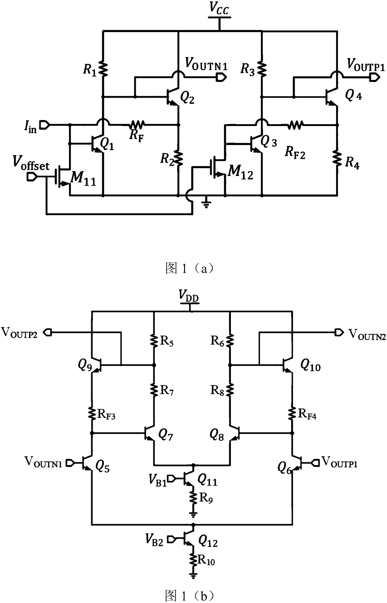
[0019] This embodiment is achieved through the following technical solutions, a high-speed optical receiver with a transmission rate of 25Gbps, including a transimpedance amplifier, Dummy, a first-stage limiting amplifier, a second-stage limiting amplifier, an output buffer stage, a DC bias remove the circuit;

[0020] The transimpedance amplifier is connected to the input photocurrent signal I in with offset cancellation current I offset1 , convert the output current signal of the photodetector into a voltage signal, and perform preliminary amplification, and output the forward voltage signal V OUTN1 ;

[0021] Dummy access offset cancellation current I offset2 , the output is a DC voltage reference signal V OUTP1 ;

[0022] The first-stage limiting amplifier is connected to the forward voltage signal V OUTN1 and DC voltage reference signal V ...


PUM


Abstract

The invention relates to an optical fiber communication technology, specifically to a high-speed optical receiver having a transmission rate of 25 Gbps. The optical receiver comprises an input photocurrent signal, a trans-resistance amplifier, a Dummy, a first-stage limiting amplifier, a second-stage limiting amplifier, an output buffer stage and DC offset cancellation circuit; the trans-resistance amplifier is connected to the input photocurrent signal, the Dummy and the first-stage limiting amplifier respectively, the Dummy is connected to the first-stage limiting amplifier, the first-stagelimiting amplifier is connected to the second-stage limiting amplifier, the second-stage limiting amplifier is connected to the output buffer stage and the DC offset cancellation circuit respectively, and the DC offset cancellation circuit is connected to the trans-resistance amplifier and the Dummy respectively. The input of the receiver adopts the form of pseudo-differential, which reduces thecommon mode noise, eliminates the disturbance caused by the inner lead coupling, improves the sensitivity and stability of the circuit, and obtains a large output swing; and a small DC offset can be maintained while the input current is high, so that the dynamic range of the circuit is increased to a certain extent.

Description

technical field [0001] The invention belongs to the technical field of optical fiber communication, in particular to a high-speed optical receiver with a transmission rate of 25Gbps. Background technique [0002] Optical fiber communication has large bandwidth, large communication capacity, good anti-interference performance, and low overall cost, which is the inevitable direction of communication development. With the development of diverse communication requirements such as cloud storage, big data, and the Internet of Things, the bandwidth of optical fiber communication continues to increase, and the development of high-speed optical fiber systems is imminent. In a typical optical fiber communication system, the optical transmitter is responsible for the generation and transmission of optical signals, the optical fiber channel is responsible for the transmission of optical signals, and the optical receiver is responsible for the reception of optical signals, including phot...

Claims


Application Information

Patent Timeline
Patent Type & Authority Applications(China)
IPC IPC(8): H04B10/60
CPCH04B10/60
Inventor 何进薛喆陈婷李硕
Owner WUHAN UNIV
Why Eureka
Try Eureka