Ring oscillator

A ring oscillator, a technology that forms a ring, is applied in the direction of electric pulse generator circuit, pulse generation, pulse technology, etc. It can solve the problems of poor performance of the ring oscillator, reduce power consumption delay product, increase output swing, improve The effect of charging speed

Active Publication Date: 2017-12-26
SOUTH CHINA UNIV OF TECH
View PDF2 Cites 2 Cited by
  • Summary
  • Abstract
  • Description
  • Claims
  • Application Information

AI Technical Summary

Problems solved by technology

[0003] In order to overcome the problem of poor performance of the existing ring oscillator composed of oxide thin film transistors, the present invention provides a low-power full-swing ring oscillator composed of a pseudo-CMOS bootstrap inverter

Method used


Image

  • Ring oscillator
  • Ring oscillator
  • Ring oscillator

Examples


Embodiment

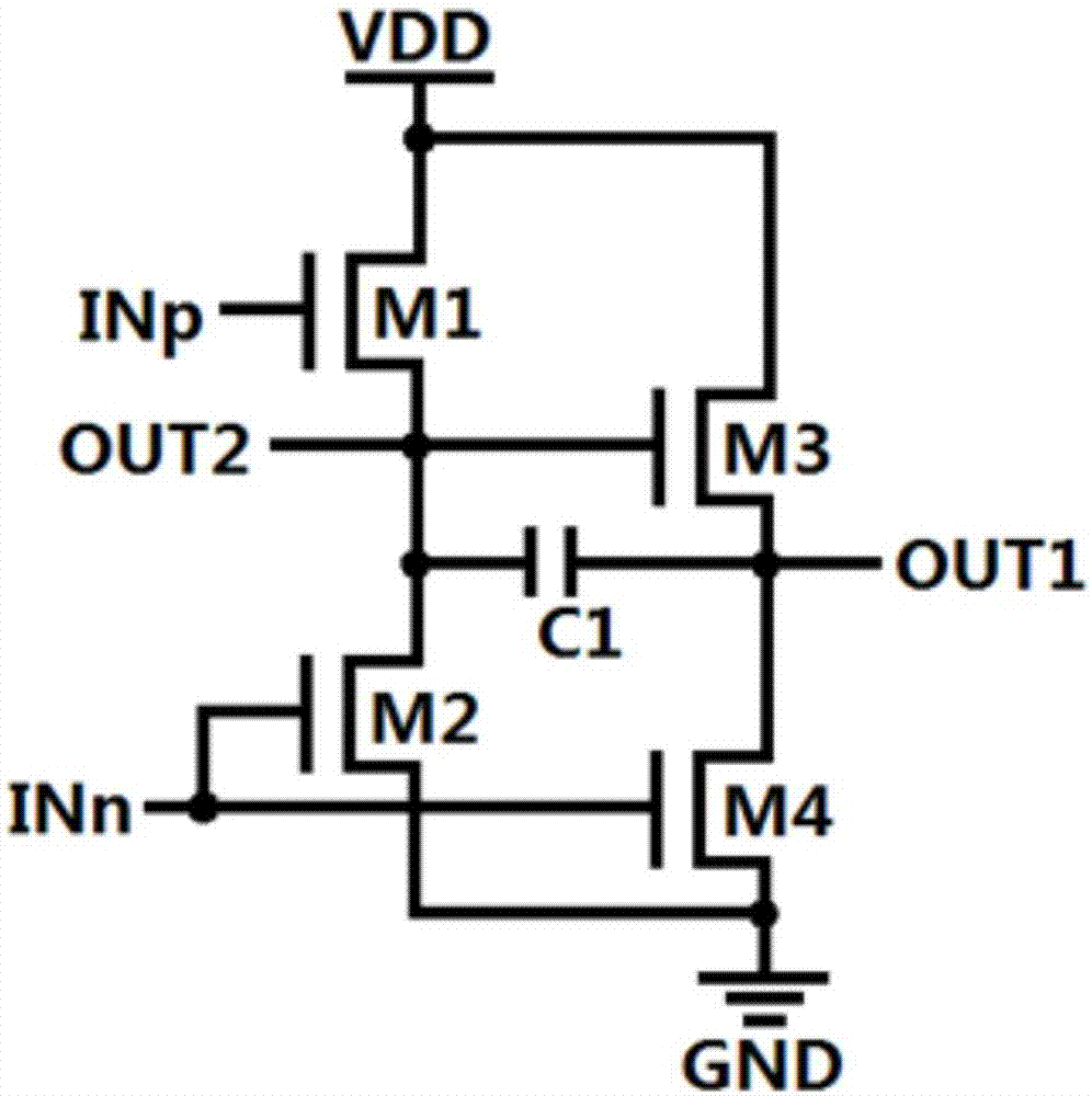
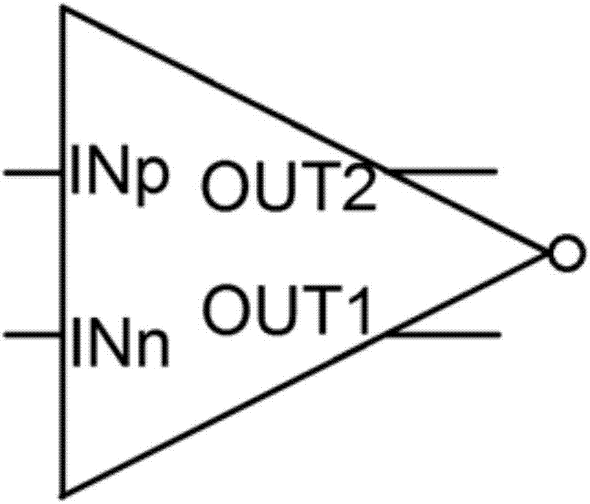
[0026] like figure 1 Shown is a circuit schematic diagram of a pseudo-CMOS bootstrap inverter, which is composed of a first transistor M1, a second transistor M2, a third transistor M3, a fourth transistor M4 and a capacitor C1. The first transistor M1 and the second transistor M2 constitute a second inverter, the first transistor M1 serves as a pull-up transistor, and the second transistor M2 serves as a pull-down transistor. The third transistor M3 and the fourth transistor M4 constitute a first inverter, the third transistor M3 serves as a pull-up transistor, and the fourth transistor M4 serves as a pull-down transistor.

[0027] The drain of the first transistor M1 is connected to the power supply terminal VDD, its gate is used as a non-inverting input port INp, its source is connected to the drain of the second transistor M2, and at the same time, it is used as a second output port OUT2, and the output voltage is the second inverter. The gate of the second transistor M2 ...


PUM


Abstract

The invention discloses a ring oscillator. The ring oscillator comprises an N-stage pseudo CMOS bootstrap inverter, wherein the pseudo CMOS bootstrap inverter is composed of a first transistor, a second transistor, a third transistor, a fourth transistor and a bootstrap capacitor, and includes four ports: a non-inverting input port, an inverting input port, a first output port and a second output port; the first transistor and the second transistor form a second inverter, and the third transistor and the fourth transistor form a first inverter; and due to the output voltage of the second inverter, the pseudo CMOS bootstrap inverter can turn off a pull-up tube of the first inverter, so that the pseudo CMOS bootstrap inverter has lower power consumption, and the output swing is increased by adding the bootstrap capacitor. The ring oscillator provided by the invention can improve the normally open state of a pull-up tube of the second inverter via a new interconnecting way, so as to further reduce the power consumption of the second inverter, reduce the power consumption delay product of the ring oscillator, and reduce the full-swing output.

Description

technical field [0001] The present invention relates to a semiconductor integrated circuit, in particular to a ring oscillator. Background technique [0002] The new oxide thin film transistor device has become a popular research object in recent years due to its excellent performance and simple manufacturing process, but the oxide thin film transistor is an N-type device, lacking a complementary P-type device, and a diode composed of an N-type transistor alone. In the inverter connected to the load, its pull-up transistor is always on, resulting in high power consumption and insufficient output swing; and due to the low mobility of the oxide thin film transistor and the large parasitic capacitance, the frequency of the clock oscillator is low. . SUMMARY OF THE INVENTION [0003] In order to overcome the problem of poor performance of the ring oscillator composed of the existing oxide thin film transistor, the present invention provides a low power consumption full swing ...

Claims


Application Information

Patent Timeline
Patent Type & Authority Applications(China)
IPC IPC(8): H03K3/03
CPCH03K3/0315
Inventor 吴建东吴为敬姚若河
Owner SOUTH CHINA UNIV OF TECH
Why Eureka
Try Eureka