
Car-track-bridge-foundation coupling system and dynamic analysis method thereof

A coupling system and vehicle system technology, applied in the field of railway engineering application calculation and design, can solve problems such as difficult multi-rigid body dynamics modeling, inability to simulate wheel-rail contact relationship, inability to overcome memory and calculation efficiency, etc.

Inactive Publication Date: 2013-06-12
CENT SOUTH UNIV +1
View PDF0 Cites 53 Cited by
  • Summary
  • Abstract
  • Description
  • Claims
  • Application Information

AI Technical Summary

Problems solved by technology

[0003] In the research of vehicle-track-bridge-foundation coupling vibration, since it is necessary to consider the complex wheel-rail contact relationship and reflect the vibration characteristics of vehicles, tracks, bridges and foundations, traditional research is limited to vehicle-track-bridge Coupled system vibration research, and limited to insurmountable memory and computational efficiency issues, the track and bridge structures have been simplified a lot
For example, the common vehicle dynamics software SIMPACK, NUCARS, etc. can easily realize the multi-body dynamics modeling of the vehicle structure, and has its own wheel-rail contact module, but it is difficult to simulate the turnout and bridge in detail
However, the current general-purpose finite element calculation software such as ANSYS, MARC, DYNIA, etc. are good at detailed finite element simulation of structures such as rails and bridges, but it is difficult to simultaneously perform multi-rigid body dynamic modeling of vehicle structures, and cannot directly Simulate the wheel-rail contact relationship
Although the self-compiled special calculation program can realize the mixed modeling of multi-body and finite element, but the types of elements are limited, it is difficult to simulate the structural details, and the modeling work is often heavy

Method used


Image

  • Car-track-bridge-foundation coupling system and dynamic analysis method thereof
  • Car-track-bridge-foundation coupling system and dynamic analysis method thereof
  • Car-track-bridge-foundation coupling system and dynamic analysis method thereof

Examples


Embodiment Construction

[0071] The present invention will be further described below in conjunction with specific embodiments and with reference to the accompanying drawings.

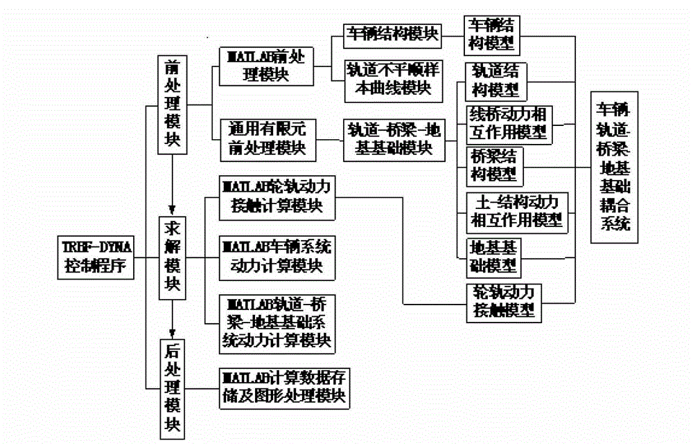
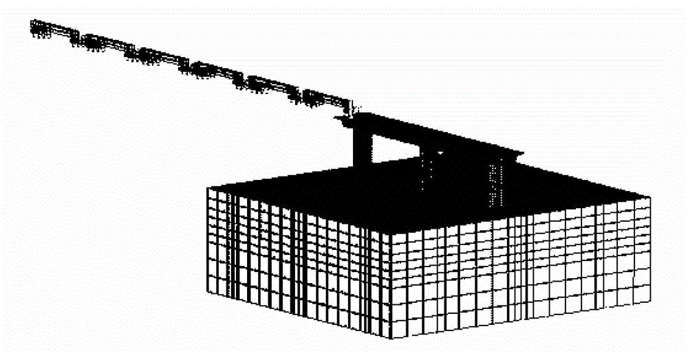
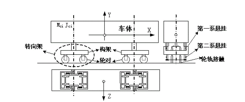
[0072] figure 1 It is a schematic structural diagram of the vehicle-track-bridge-foundation coupling system of the embodiment of the present invention, such as figure 1 As shown, the vehicle-track-bridge-foundation coupling system includes the vehicle structure model, the track structure model, the bridge structure model, the foundation model, the wheel-rail dynamic contact model between the wheel and the track rail, and the line between the track and the bridge The bridge dynamic interaction model and the soil-structure dynamic interaction model between the bridge and the foundation. The TRBF-DYNA control module controls the pre-processing module, solving module and post-processing module. The pre-processing module is composed of MATLAB vehicle structure module and MATLAB track irregularity The sample curve module is impleme...


PUM


Abstract

The invention relates to a car-track-bridge-foundation coupling system. A pre-processing module is realized through an MATLAB car structure module and an MATLAB track irregularity sample curve module. A track-bridge-foundation module is realized based on general finite-element software and comprises a track structure model, a track-bridge dynamic interaction model, a bridge structure model, a soil-structure dynamic interaction model and a foundation model. A solving module is realized through an MATLAB wheel-rail dynamic contact calculation module, an MATLAB car system dynamic calculation module and an MATLAB track-bridge-foundation system dynamic calculation module, wherein the MATLAB wheel-rail dynamic contact calculation module is simulated through a track dynamic contact model. A post-processing module is realized through an MATLAB calculation data storage and graphic processing module. Therefore, the car-track-bridge-foundation coupling system is formed.

Description

technical field [0001] The invention relates to a dynamic analysis method of a vehicle-track-bridge-foundation coupling system based on a vehicle-track-bridge-foundation spatial coupling model, and belongs to the technical field of railway engineering application calculation and design. Background technique [0002] Due to the high speed of trains on existing lines, newly-built passenger dedicated lines and high-speed railways, in order to meet the requirements of driving safety and riding comfort, the relevant design codes have higher requirements for track smoothness and rigidity of the under-rail structure; at the same time, from In terms of environmental protection, land saving, site soil conditions, terrain, etc., countries with developed high-speed rail transportation such as China, France, Germany, and Japan often use viaducts as the substructure of the track in passenger dedicated lines and high-speed rail lines. Taking the Beijing-Shenzhen-Hong Kong Passenger Dedica...

Claims


Application Information

Patent Timeline
Patent Type & Authority Applications(China)
IPC IPC(8): G06F17/50
Inventor 朱志辉
Owner CENT SOUTH UNIV
Learn More