
A Ridge Waveguide Filter with High Microdischarge Threshold and Its Design Method

A technology of ridge waveguide and filter, which is applied in the field of ridge waveguide filter and its design, can solve the problems of payload failure, high-power microwave component failure, and high electric field intensity, and achieve volume and weight reduction and suppress micro-discharge effect , The effect of high micro-discharge threshold

Active Publication Date: 2014-10-08
XIAN INSTITUE OF SPACE RADIO TECH
View PDF5 Cites 0 Cited by
  • Summary
  • Abstract
  • Description
  • Claims
  • Application Information

AI Technical Summary

Problems solved by technology

Micro-discharge effects are prone to occur in areas with strong internal electric fields in high-power microwave components of spacecraft such as multiplexers and filters, resulting in failure of high-power microwave components, and even complete failure of the entire payload
The ridge waveguide filter is very suitable for use in satellite payloads due to its wide bandwidth and small size. However, the distance between the ridge and the metal wall of the ridge waveguide filter is small, and the electric field strength is large, which is prone to micro-discharge effects and affects the satellite payload. safe and reliable operation
[0003] The electric field strength between the ridge and the cover plate of the traditional ridge waveguide low-pass filter is large, and the distance is small, which is prone to micro-discharge effect

Method used


Image

  • A Ridge Waveguide Filter with High Microdischarge Threshold and Its Design Method
  • A Ridge Waveguide Filter with High Microdischarge Threshold and Its Design Method
  • A Ridge Waveguide Filter with High Microdischarge Threshold and Its Design Method

Examples


Embodiment

[0036] Embodiment: In the range of 2.3-2.5GHz, the reflection loss is less than -20dB, and the commonly used ridge waveguide filter with insertion loss less than 0.15dB is an example. The design process of the ridge waveguide filter proposed by the present invention is as follows:

[0037] (1) According to the technical specifications, the cut-off frequency f c =2.5GHz, impedance R 0 =50Ω, insertion loss less than 0.15dB, etc. It is required to determine the filter order N=6, and determine the lumped parameter low-pass filter circuit through table lookup or calculation, such as Image 6 shown;

[0038] The value of the inductance element is shown in Table 1:

[0039] Table 1 Values ​​of inductive components in lumped parameter filter circuits

[0040] L1

L2

L3

L4

L5

L6

31.08nH

84.93nH

116.0nH

116.0nH

84.93nH

31.08nH

[0041] The values ​​of the capacitive components are shown in Table 2:

[0042] Table 2 Value...


PUM


Abstract

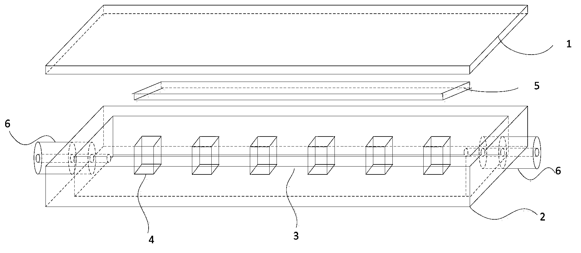
The invention relates to a ridge waveguide filter with a high micro discharging threshold value and a design method thereof. The ridge waveguide filter with the high micro discharging threshold value comprises a cover plate, a filter outer casing, rectangular waveguides, a plurality of sections of ridge waveguides, a filling layer and TNC connectors (threaded Neil-Concelman connector), wherein the inner surface of the cover plate needs to be flattened, the ridge waveguides are connected by the rectangular waveguides, the input ends and the output ends of the ridge waveguides are respectively assembled with each TNC connector, and a polyetherimide material is filled between a ridge of each ridge waveguide and the cover plate. The design method of the filter comprises the following steps of (1) firstly, according to the design parameter requirements of the filter, such as center frequency, working bandwidth and out-of-band inhibition, looking up a table to obtain a lumped parameter model of the filter; (2) carrying out impedance inverting on a filter circuit of the lumped parameters; (3) using the ridge waveguides to replace the lumped parameter elements, such as capacitors and inductors; (4) using the rectangular waveguide structure to realize an impedance inverter; (5) filling the polyetherimide material between the ridge of each ridge waveguide and the cover plate; and (6) optimizing the size of the ridge waveguide filter.

Description

technical field [0001] The invention provides a ridge waveguide filter with high micro-discharge threshold and a design method thereof, belonging to the field of microwave technology. Background technique [0002] The micro-discharge effect, also known as the secondary electron multiplication effect, refers to the secondary electron emission and multiplication effect excited by electrons between two metal surfaces or on the surface of a single medium under the acceleration of an external radio frequency field under vacuum conditions. According to different mechanisms, the micro-discharge effect can be divided into bimetallic surface micro-discharge effect and single-dielectric surface micro-discharge effect. Spacecraft high-power microwave components are prone to bimetallic surface micro-discharge effect. Microdischarge effects are prone to occur in areas with strong internal electric fields of high-power microwave components such as multiplexers and filters in spacecraft, r...

Claims


Application Information

Patent Timeline
Patent Type & Authority Patents(China)
IPC IPC(8): H01P1/207H01P11/00
Inventor 胡天存崔万照夏亚峰
Owner XIAN INSTITUE OF SPACE RADIO TECH
Learn More