Hydraulic pressure control device

A control device and hydraulic technology, applied in valve devices, valve operation/release devices, brakes, etc., can solve problems such as difficulty in reducing the size of the hydraulic control device, increasing the housing of the electronic control unit, and requiring a leaf spring installation process. , to achieve the effect of increasing elastic deformation energy, shaking restraint, and improving the stability of fixation

Active Publication Date: 2013-06-19
ADVICS CO LTD
View PDF6 Cites 8 Cited by
  • Summary
  • Abstract
  • Description
  • Claims
  • Application Information

AI Technical Summary

Problems solved by technology

[0009] The fixing structure of the electromagnet coil described in the above-mentioned patent documents 1 and 2, and the fixing structure using a rubber ball or the like as an elastic supporting member need to ensure a storage space for the elastic supporting member, thereby increasing the housing of the electronic control unit, and It is difficult to achieve further size reduction of the hydraulic control device
Also, the number of parts increases
[0010] In

Method used


Image

  • Hydraulic pressure control device
  • Hydraulic pressure control device
  • Hydraulic pressure control device

Examples


Example Embodiment

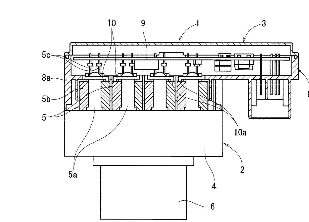
[0028] Below, based on the attached Figure 1~Figure 4 Embodiments of the hydraulic control device of the present invention will be described. figure 1 It is an outline showing an example of a hydraulic control device. The hydraulic control device 1 is composed of a hydraulic unit 2 and an electronic control unit 3 .

[0029] The hydraulic unit 2 is configured by assembling a pump (not shown) and a main body 5 a of a solenoid valve 5 for hydraulic control to a hydraulic block (casing) 4 , and attaching a motor 6 for driving the pump to one side of the hydraulic block 4 . surface. Inside the hydraulic block 4, a pressure sensor, a buffer, a low-pressure reservoir, etc. are assembled as needed.

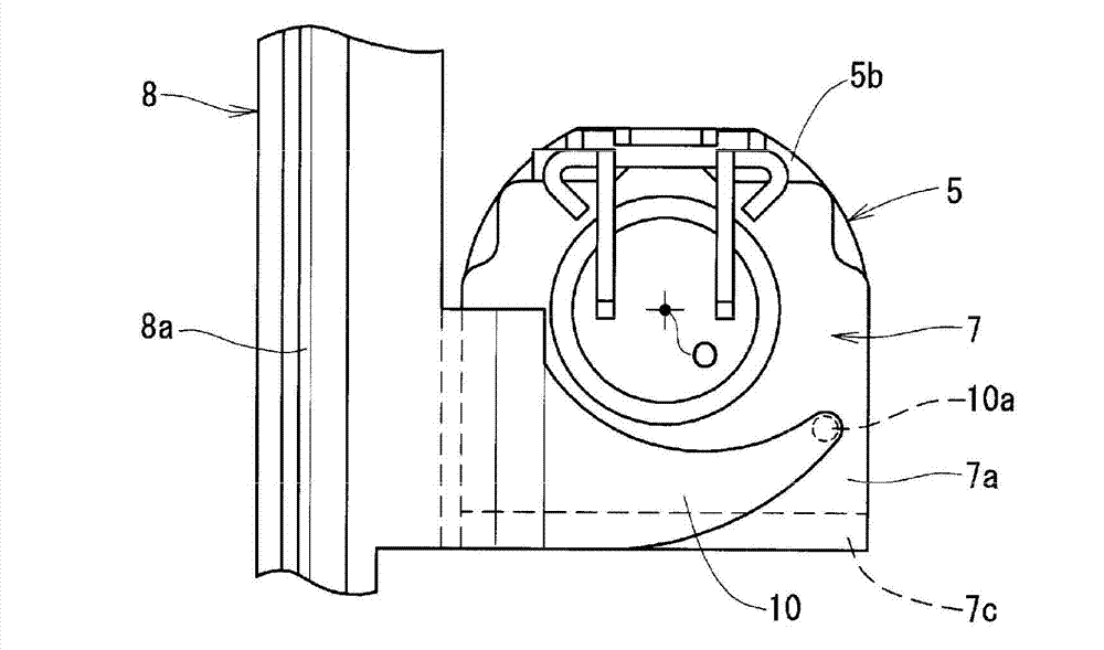
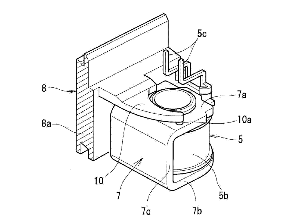
[0030] The main body 5a of the solenoid valve protrudes toward the outside of the hydraulic block, and the solenoid coil 5b is fitted outside the outer periphery of the protruding portion. The electromagnet coil 5b adopts a coil and a yoke 7 (refer to figure 2 , image 3 ) combin...


PUM


Abstract

A hydraulic pressure control device includes: a hydraulic pressure unit, in which a solenoid valve for hydraulic pressure control is assembled with a hydraulic pressure block; and an electronic control unit, which includes a circuit board having a drive control circuit of the solenoid valve and stored inside a resin case, wherein a solenoid coil is fit onto the main body of the solenoid valve fixed to the hydraulic pressure block of hydraulic pressure unit, and wherein the solenoid coil is elastically pressed against and fixed to the hydraulic pressure block by a coil pressing arm integrally formed with the resin case.

Description

technical field [0001] The present invention relates to a hydraulic control device composed of a hydraulic unit and an electronic control unit. Specifically, an electromagnet coil is embedded outside the main body of the solenoid valve fixed on the hydraulic block (housing) of the hydraulic unit, and the electromagnetic coil is The type of hydraulic control device in which the force of the component holds the solenoid coil. Background technique [0002] As a hydraulic control device used for a brake for a vehicle, there are hydraulic control devices such as those shown in Patent Documents 1 and 2 below, for example. [0003] This hydraulic control device is composed of a hydraulic unit and an electronic control unit. The hydraulic unit assembles a solenoid valve for hydraulic control, a pump, and a motor for driving the pump to a hydraulic block. The circuit board of the drive control circuit is housed inside the resin case. [0004] The solenoid valve fixes its main body ...

Claims


Application Information

Patent Timeline
IPC IPC(8): B60T8/36
CPCF16K27/029B60T8/368F16K31/046
Inventor 小河真仁山村鲇美土方昌幸矢内浩二
Owner ADVICS CO LTD
Why Eureka
Try Eureka