Strengthened glass, touch panel and method of manufacturing strengthened glass

A technology for strengthening glass and manufacturing methods, which is applied to glass manufacturing equipment, glass tempering, manufacturing tools, etc., can solve the problems of prolonging processing time, reducing production efficiency, and accompanying danger, and achieve shortening processing time, improving production efficiency, Reliable Broken Effects

Inactive Publication Date: 2013-06-19
MICRO TECH CO LTD
View PDF5 Cites 14 Cited by
  • Summary
  • Abstract
  • Description
  • Claims
  • Application Information

AI Technical Summary

Problems solved by technology

[0005] However, this etching treatment must be performed on the entire cut surface (four sides except the front and back sides of the glass plate) of the tempered glass that has been separated into pieces, and since the concentration of the chemical solution used is low, it is difficult to It takes a long time until the etching process is completed to remove microcracks, etc.
In addition, although it is possible to increase the concentration of the chemical solution in order to shorten the treatment time, it is not only dangerous, but also a strong corrosion reaction will occur, and large unevenness will be generated on the cut surface to be etched.
As such, there is a problem in the conventional manufacturing method of strengthened glass that after cutting the glass plate, the process for maintaining the strength of the strengthened glass takes a long time, and the production efficiency is greatly reduced
However, according to this method, after the large glass substrate is cut, the edge portion of the substrate is ground to remove the protrusion portion remaining on the edge portion of the substrate, and then the edge surface of the substrate is etched. Etching treatment, thus prolonging processing time and reducing production efficiency

Method used


Image

  • Strengthened glass, touch panel and method of manufacturing strengthened glass
  • Strengthened glass, touch panel and method of manufacturing strengthened glass
  • Strengthened glass, touch panel and method of manufacturing strengthened glass

Examples


Embodiment Construction

[0039] Hereinafter, modes for implementing the present invention will be described with reference to the drawings.

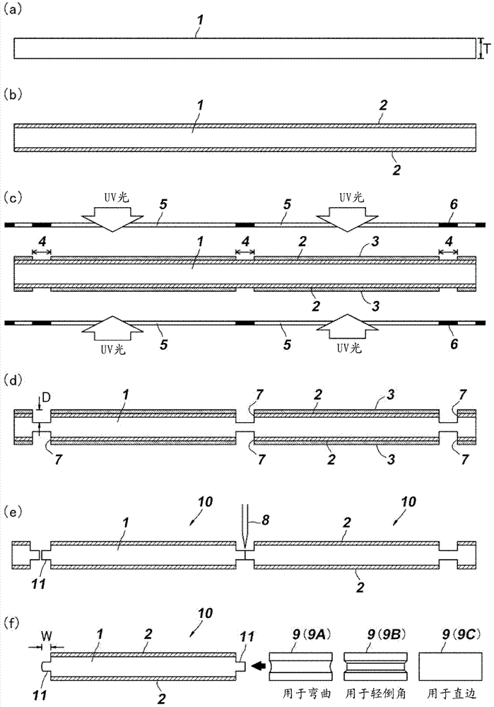
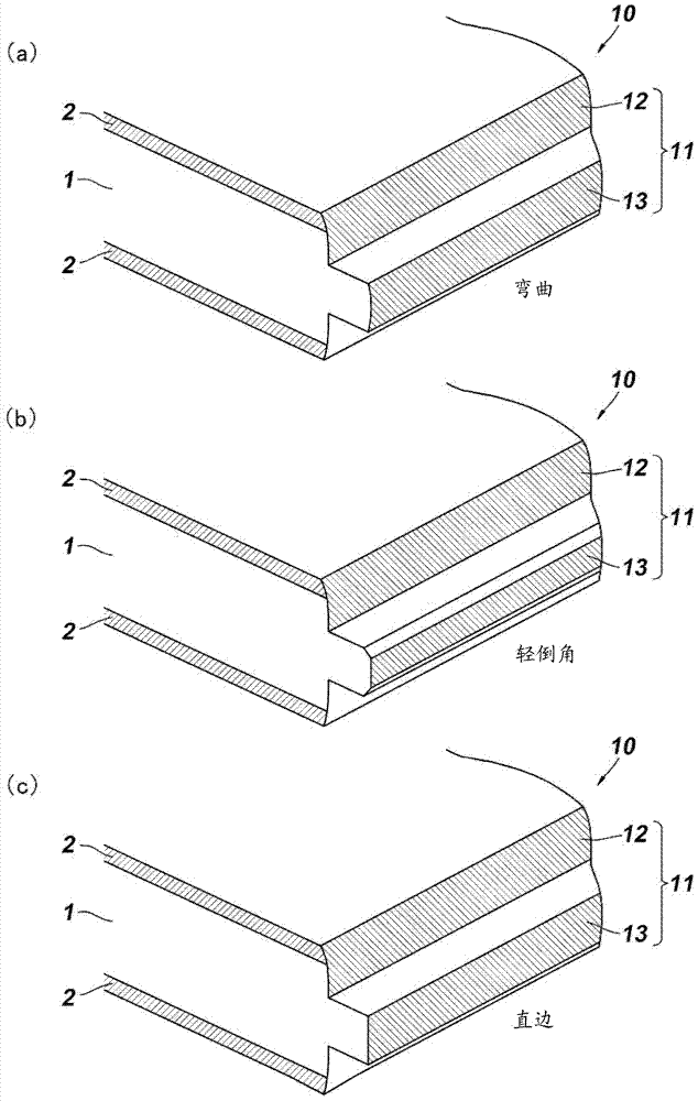
[0040] Such as figure 1 As shown in , in the present invention, a thin and large glass plate 1 is used, and the single glass plate 1 is separated into pieces to manufacture a plurality of tempered glasses 10 , 10 , . . . . Hereinafter, the manufacturing method thereof will be described in the order of steps. In addition, in the drawings referred to in the following description, in order to clarify the structure, the ratio of the actual size is different, and the characteristic part is enlarged compared with other parts.

[0041] Such as figure 2 As shown in (a), first, a thin and large glass plate 1 is prepared. The plate thickness T of the glass plate 1 is not particularly limited, but is preferably 0.4 to 1.0 mm in consideration of the need for thinning, processing characteristics, and the like. In addition, if the thickness of the glass plate 1 is 0.4 mm...


PUM


Abstract

There is provided a strengthened glass capable of shortening a process time for maintaining the strength to improve the production efficiency and forming an edge surface of the strengthened glass in any shape while preventing damage such as fracture due to micro-cracks or the like. Strengthening layers 2 are formed on both surfaces of the glass plate 1, and protection films 3 are formed in regions except for cutting portions 4. Subsequently, recessed portions 7 are formed by etching both surfaces of the glass plate at the cutting portions 4 of the glass plate 1 not covered by the protection films 3. Subsequently, the glass plate 1 is cut using a cutter 8 along the recessed portions 7 to form separated strengthened glass 10, and a stepped portion 11 having a protruding cutting surface and including an interior side surface 12 formed by etching a periphery of the glass plate 1 and an exterior side surface 13 formed by mechanical cutting is formed. Also, an edge portion of the stepped portion 11 may be formed in any shape by mechanical machining.

Description

technical field [0001] The present invention relates to tempered glass provided with reinforcing layers on both sides of a glass plate, and relates to the ability to prevent damage such as cracks and the like due to microcracks or chipping that occur when the glass plate is cut, and to ensure Reinforced glass with high stress strength, a touch panel using the strengthened glass, and a method of manufacturing the strengthened glass. Background technique [0002] In recent years, among electronic devices such as smartphones, tablet-type terminals, car navigation devices, and the like, a large number of touch panel-mounted products are sold. Generally, a touch panel is constituted by bonding a cover glass and an electrostatic sensor, and the cover glass is characterized by being as thin as possible and having high strength against stress. [0003] Reinforced glass is known as such a high-strength glass. Reinforced glass refers to glass in which compressive stress layers (rein...

Claims


Application Information

Patent Timeline
Patent Type & Authority Applications(China)
IPC IPC(8): C03C21/00C03B27/012C03C15/00C03B33/02G06F3/041
CPCC03B33/023C03B33/07C03B33/074C03C15/00C03C17/002C03C2218/34Y10T428/24488Y02P40/57G06F3/041G06F2203/04103
Inventor 吉川实
Owner MICRO TECH CO LTD
Why Eureka
Try Eureka