A construction method of high-pressure rotary spraying hollow reinforced pipe pile and high-pressure rotary sprayed hollow reinforced pipe pile

A technology of high-pressure rotary grouting piles and high-pressure rotary grouting, which is applied to sheet pile walls, foundation structure engineering, construction, etc., can solve the problems of low overall strength of steel pipe piles, poor bonding effect of steel pipes and rotary grouting bodies, etc., and achieve construction The method is simple and efficient, saves the amount of grouting engineering in the later stage, and has the effect of low cost

Active Publication Date: 2015-08-26
POWERCHINA ZHONGNAN ENG
View PDF6 Cites 0 Cited by
  • Summary
  • Abstract
  • Description
  • Claims
  • Application Information

AI Technical Summary

Problems solved by technology

[0005] In order to overcome the disadvantages of poor bonding effect between the steel pipe and the rotary spraying body and low overall strength of the steel pipe pile caused by the existing steel pipe sinking method, the present invention aims to provide a construction method for high-pressure rotary spraying hollow reinforced pipe pile. The construction method adopts the vibrating method to effectively bond the hollow reinforcement pipe and the high-pressure jet body into a whole, and extend the hollow reinforcement pipe into the bedrock to form a highly stable pile structure

Method used


Image

  • A construction method of high-pressure rotary spraying hollow reinforced pipe pile and high-pressure rotary sprayed hollow reinforced pipe pile
  • A construction method of high-pressure rotary spraying hollow reinforced pipe pile and high-pressure rotary sprayed hollow reinforced pipe pile
  • A construction method of high-pressure rotary spraying hollow reinforced pipe pile and high-pressure rotary sprayed hollow reinforced pipe pile

Examples


Embodiment Construction

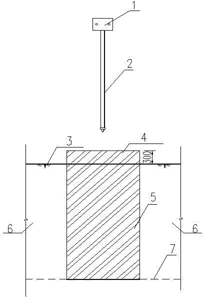
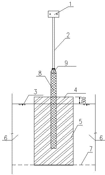
[0034] A construction method of high-pressure rotary grouting steel pipe piles, taking Jiangsu Liyang Pumped Storage Power Station as an example, the homogeneous earth dam crest elevation of the reservoir under the power station is 24.4m, the reservoir bottom elevation is -2.0m, and the normal storage level elevation is 19.0m , dead water elevation 0m.

[0035] The geological conditions of the dam foundation are extremely complex, with the thickness of silty clay in the upper part ranging from 2.0 to 5.0m, the thickness of silty clay ranging from 0 to 8.0m, and the thickness of sand, pebble and gravel layer from 2.20 to 5.50m. The silty soil is distributed at an elevation of 7.0-15.0m, located below the water level of the reservoir, and the silty clay is thicker in the area around 350m long on the north side of the homogeneous earth dam, which is 3-8m.

[0036] Considering factors such as the tight construction period and complex stratum conditions at the site, the constructio...


PUM


Abstract

The invention discloses a construction method of a high pressure jet grouting hollow strengthening tubular pile and the high pressure jet grouting hollow strengthening tubular pile. For solving the problems that an existing steel tube submergence method leads to bad adhesive effect between a hollow strengthening pipe and a jet grouting body, and the entire rigidity of a tubular pile is low, the construction method of the high pressure jet grouting hollow strengthening tubular pile comprises the following steps: (1) forming a high pressure jet grouting tubular pile, (2), communicating the hollow strengthening pipe and a high spraying grouting pipe of a high spraying grouter; and (3), placing the hollow strengthening pipe into a high pressure jet grouting pile body before cement slurry is initially set, and the bottom end of the hollow strengthening pipe is located below a bed rock boundary. The high pressure jet grouting hollow strengthening tubular pile adopts the construction method of the high pressure jet grouting hollow strengthening tubular pile. The construction method of the high pressure jet grouting hollow strengthening tubular pile and the high pressure jet grouting hollow strengthening tubular pile adopt a vibroflotation method to effectively adhere both the steel tube and the high pressure jet grouting body to an integration, extend the steel tube into the bed rock, and form a pile body structure with high stability.

Description

technical field [0001] The invention relates to a construction method of high-pressure rotary spraying hollow reinforced pipe piles, which is mainly suitable for treating soft foundations with a depth less than 20m. Background technique [0002] The high-pressure rotary grouting method is a new method full of vitality in the soft foundation reinforcement treatment. It mainly uses a high-spray grouting machine to sink the high-spray grouting pipe into the ground to a predetermined depth, and then sprays the high-pressure rotary grout into the soil layer and mixes with the soil to form Continuously lapped cement reinforcement. This method has high construction efficiency and is especially suitable for the reinforcement of weak soil layers such as alluvium, diluvial layer, residual layer and artificial filling in the Quaternary Period, and has been more and more widely used by people. However, for high-pressure rotary grouting piles, for fibrous and dense humus soils and silt ...

Claims


Application Information

Patent Timeline
Patent Type & Authority Patents(China)
IPC IPC(8): E02D5/22E02D5/46
Inventor 刘昊宁永升冯树荣钟筱贤陈洪来
Owner POWERCHINA ZHONGNAN ENG
Why Eureka
Try Eureka