
Device and method for operating a hand-held working apparatus

A working instrument and hand-held technology, which is applied in the field of operation of hand-held working instruments

Active Publication Date: 2013-06-19
ANDREAS STIHL AG & CO KG
View PDF5 Cites 7 Cited by
  • Summary
  • Abstract
  • Description
  • Claims
  • Application Information

AI Technical Summary

Problems solved by technology

Such a single determined engagement speed can be changed, for example, by user error (which causes excessive wear)

Method used


Image

  • Device and method for operating a hand-held working apparatus
  • Device and method for operating a hand-held working apparatus
  • Device and method for operating a hand-held working apparatus

Examples


Embodiment Construction

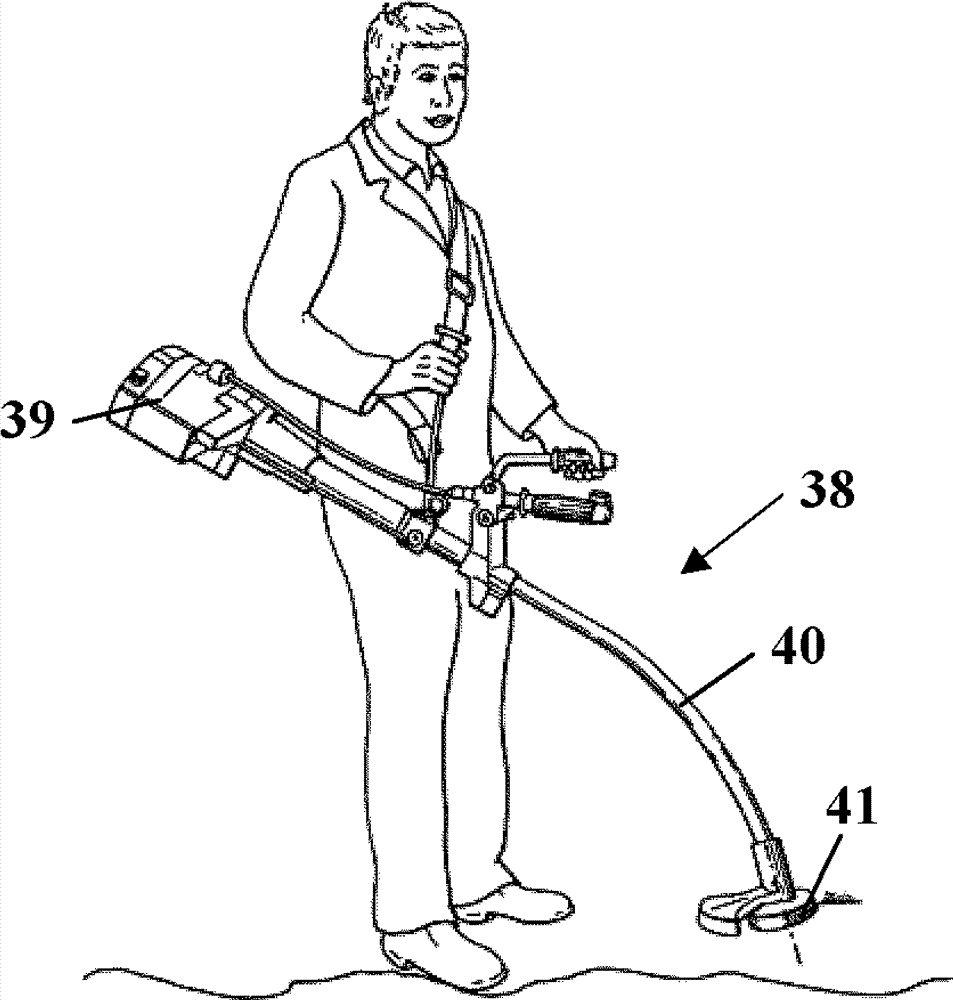
[0025] figure 1 A cutting machine 1 is shown as an example for a hand-held power tool. The cutter 1 has a housing 2 to which a rear handle 3 and a handle tube 4 are fastened via anti-vibration elements, not shown. A throttle lever 17 and a throttle lever lock 18 are arranged on the rear handle 3 . Arranged in the housing 2 are the figure 1 The internal combustion engine 9 shown schematically in FIG. 1 is constructed as a single-cylinder two-stroke engine. Protruding from the casing 2 is a starting handle 6, through which the starting handle can be manipulated in the figure 2 The starting device 23 for the internal combustion engine 9 is shown in FIG. A bracket 5 is arranged on the housing 2 , and a protective cover 7 is arranged at its forwardly protruding end. The protective hood 7 overlaps the cutting disk 8 , which is rotatably mounted on the carrier 5 . The cutting disc 8 is driven by the internal combustion engine 9 via the figure 2 Driven by a drive belt 22 show...


PUM


Abstract

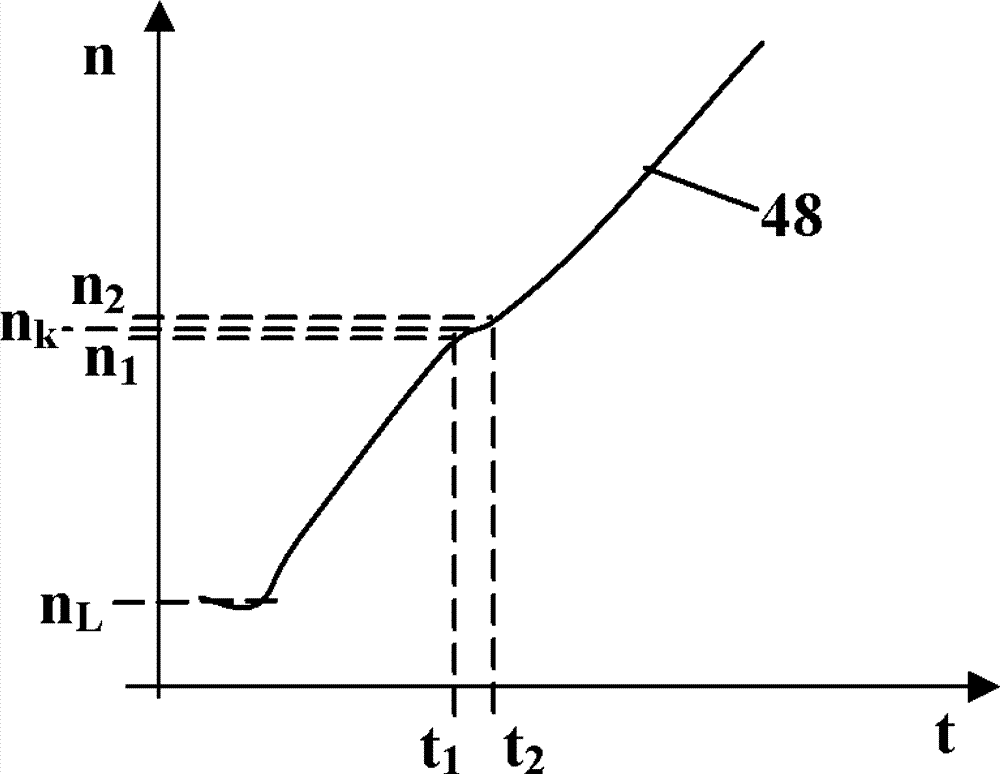
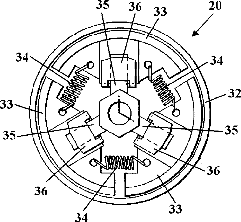
The invention relates to a method for operating a hand-held working apparatus. A hand-held working apparatus has an internal combustion engine having a crankshaft which is driven in rotation. The crankshaft drives at least one tool of the working apparatus via a centrifugal clutch. The working apparatus has a device for determining the speed of the internal combustion engine and a control device which controls the internal combustion engine. It is provided that the profile of the speed of the internal combustion engine is evaluated by the control device, and that the engagement speed of the centrifugal clutch is determined from the profile of the speed of the internal combustion engine.

Description

technical field [0001] The invention relates to a method for operating a hand-held power tool. Background technique [0002] An internal combustion engine is known from DE 10 2004 051 259 A1, which drives a tool (Werkzeug, sometimes called a knife) of a hand-held power tool via a centrifugal clutch. In order to avoid excessive heating of the centrifugal clutch during engagement, it is provided to monitor how long the rotational speed stays in a rotational speed band from the beginning of the engagement process until the end of the engagement process, and to engage in a controlled manner if the dwell time is too long. The lower and upper speeds of the speed band are permanently stored in the control circuit (Steuerschaltung). [0003] For hand-held power tools, the engagement speed is usually determined during production or in the after-sales service in that the operator accelerates the internal combustion engine into the region of the engagement speed by partially targeted ...

Claims


Application Information

Patent Timeline
Patent Type & Authority Applications(China)
IPC IPC(8): F02D31/00
CPCF02P5/1508F02D31/008F02D2400/06Y02T10/40F02D45/00
Inventor M.哈雷尔H.德施纳R.贝克
Owner ANDREAS STIHL AG & CO KG
Learn More