

Gas-fired shock wave ash removal device in petroleum refining
A technology of gas shock wave and soot blowing device, applied in combustion method, combustion product treatment, removal of solid residue, etc. The problem of shutting down the furnace to clear the ash, etc., achieves the effect of good purging effect, small maintenance and wide application range.
Inactive Publication Date: 2013-06-19
西安新生代油田信息工程有限公司
View PDF0 Cites 2 Cited by
- Summary
- Abstract
- Description
- Claims
- Application Information
AI Technical Summary
Problems solved by technology
[0002] The catalytic cracking unit is an extremely important secondary processing unit in a refinery, and its energy consumption level has a significant impact on the entire plant. Now, the CO boiler is used to delay the regeneration of the unit’s CO-rich gas and introduce it into the furnace for combustion, while utilizing the potential of lung heat Steam is generated, but due to the large amount of catalyst dust in the flue gas, when the CO boiler recovers the heat of the flue gas, the high-temperature superheating tube and the economizer tube are extremely dusty, and the existing soot blowing device cannot meet the requirements. Generally, it takes about two months to shut down the furnace to clean the dust
Method used
View moreImage
Smart ImageViewing Examples

Examples
Embodiment Construction
[0009] The present invention will be described in detail below in conjunction with the accompanying drawings and specific embodiments.
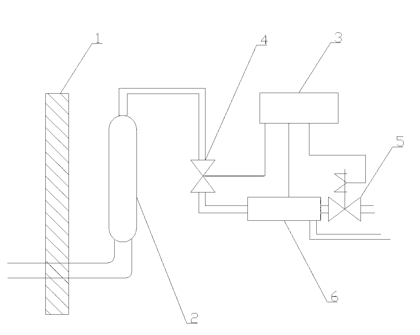
[0010] see figure 1 , the present invention includes a shock wave generator 2, a mixer 6, and an igniter 4. Air and gas are respectively communicated with the mixer 6 through two intake pipes, and the other end of the mixer 6 is connected to the shock wave generator 2 through the igniter 4. , the lower end of the shock wave generator 2 is pierced in the furnace wall 1 through a pipeline; the inlet pipeline of the mixer 6 is provided with a solenoid valve 5 .
[0011] The above-mentioned solenoid valve 5 , mixer 6 and igniter 4 are respectively connected with the control cabinet 3 .
Login to View More PUM
 Abstract
The invention relates to a gas-fired shock wave ash removal device in petroleum refining. In the prior art, gas rich in CO is regenerated and introduced into a furnace to burn in a delay mode by using a CO furnace, vapor is generated by using waste heat at the same time, but due to the fact that fume comprises a great amount of catalyst dust, on the condition that the CO furnace recycles fume heat, a high-temperature superheater tube and an economizer tube deposition are very serious, the existing ash removal device cannot meet requirements, and generally the furnace needs to be stopped for ash removal every two months. The gas-fired shock wave ash removal device in the petroleum refining comprises a shock wave generator, a mixer and an igniter. Air and fuel gas are respectively communicated with the mixer through two air inlet pipelines. The other end of the mixer is connected with the shock wave generator through the igniter. The lower end of the shock wave generator is arranged inside a furnace wall in a penetrating mode through pipelines. A magnetic valve is arranged on the air inlet pipeline of the mixer. The gas-fired shock wave ash removal device in the petroleum refining is wide in range of application, good in ash removal effect and small in maintenance.
Description
technical field [0001] The invention relates to a gas shock wave soot blowing device in petroleum refining. Background technique [0002] The catalytic cracking unit is an extremely important secondary processing unit in a refinery, and its energy consumption level has a significant impact on the entire plant. Now, the CO boiler is used to delay the regeneration of the unit’s CO-rich gas and introduce it into the furnace for combustion, while utilizing the potential of lung heat Steam is generated, but due to the large amount of catalyst dust in the flue gas, when the CO boiler recovers the heat of the flue gas, the high-temperature superheating tube and the economizer tube are extremely dusty, and the existing soot blowing device cannot meet the requirements. Generally, it takes about two months to shut down the furnace to clean the dust. Contents of the invention [0003] The technical problem solved by the invention is to provide a gas shock wave soot blowing device in...
Claims
Login to View More Application Information
Patent Timeline
 Patent Type & AuthorityApplications(China)
IPC IPC(8): F23J3/00
Inventor呙平勃赵继平党广元李建峰
Owner西安新生代油田信息工程有限公司