Optical fiber splicer

A technology of optical fiber splices and optical fibers, which is applied in the field of optical fiber connection devices, can solve the problems of long-term reliability decline, failure of optical fiber docking, and easy breakage of bare fibers, etc., and achieve the effect of simple structure, high quality of docking, and low price

Inactive Publication Date: 2013-06-19
XIAN JINHE OPTICAL TECH
View PDF1 Cites 9 Cited by
  • Summary
  • Abstract
  • Description
  • Claims
  • Application Information

AI Technical Summary

Problems solved by technology

However, the optical fiber docking device disclosed in this patent still has problems in actual use. The optical fiber docking device can only clamp the bare fiber part of the optical fiber and align the optical fiber, but there will be a gap between the bare fiber and the optical fiber that has not removed the coating layer. Leave a gap. Anyone who knows a little about optical fibers knows that without the protection of the coating l

Method used


Image

  • Optical fiber splicer
  • Optical fiber splicer
  • Optical fiber splicer

Examples


Embodiment 1

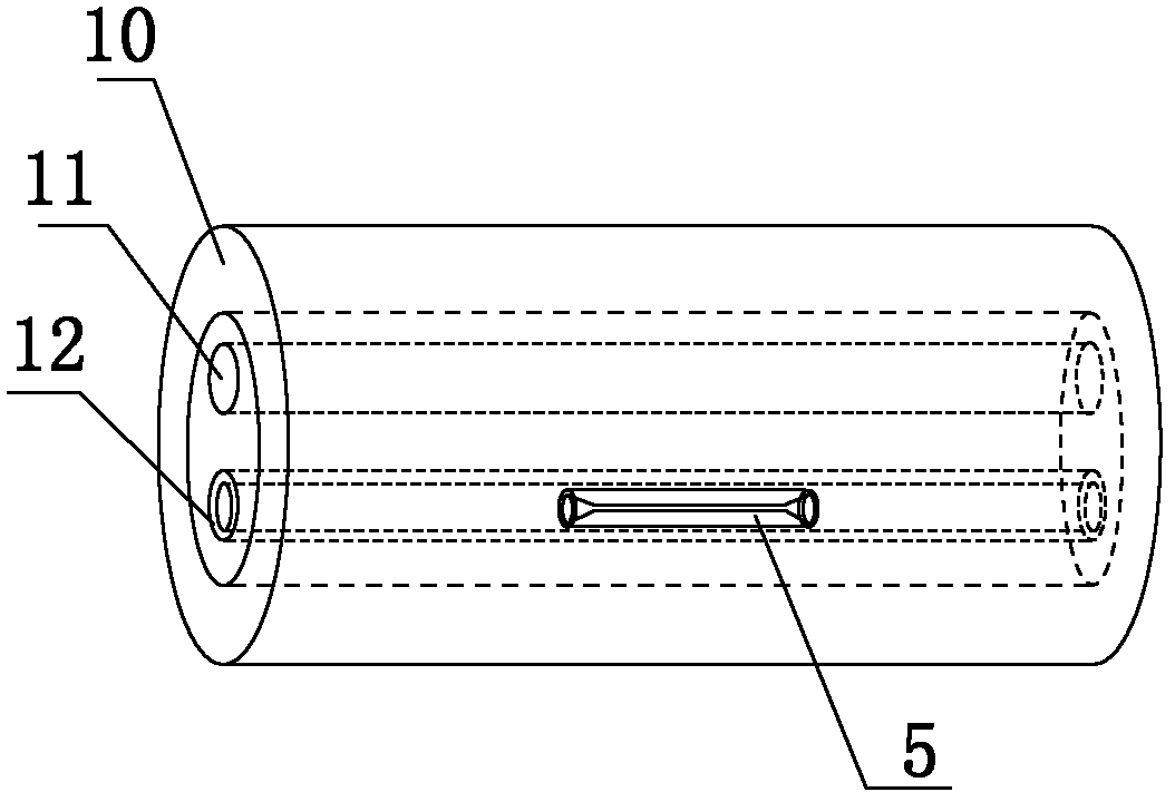
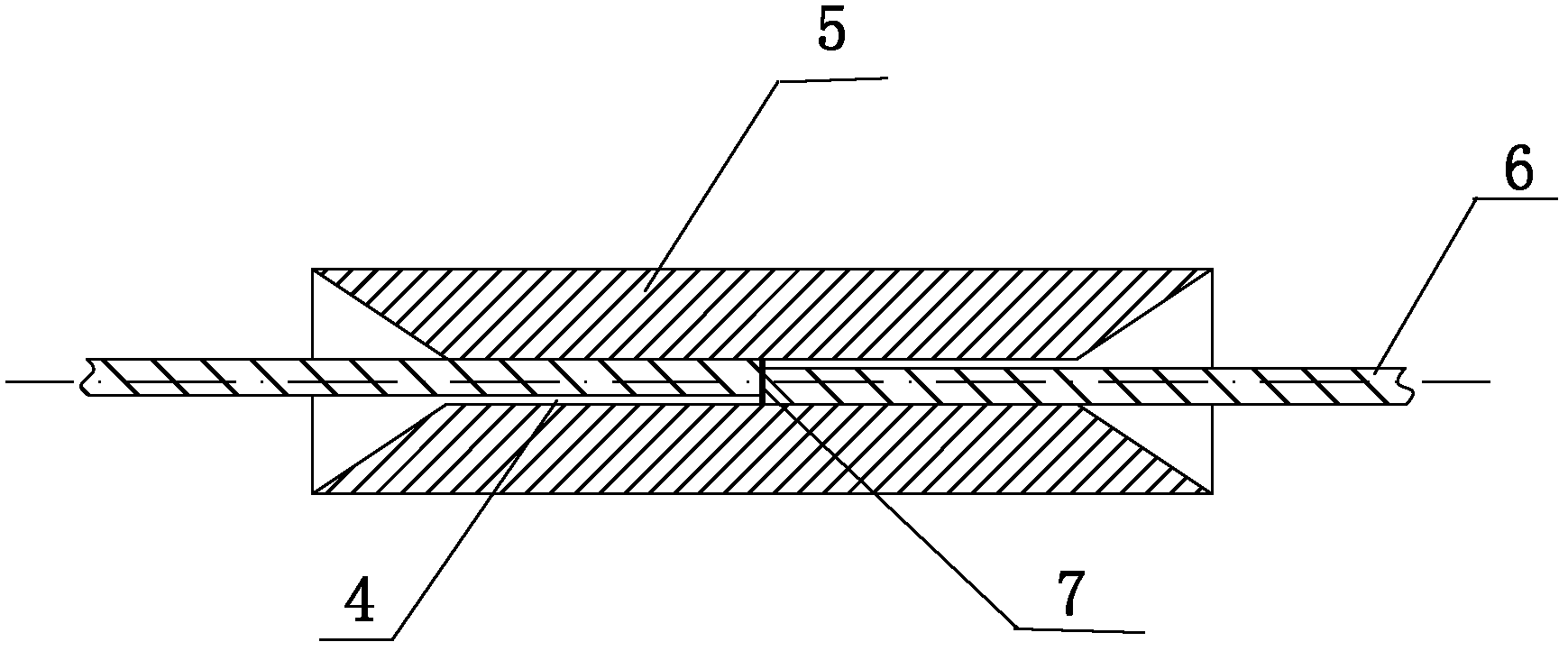
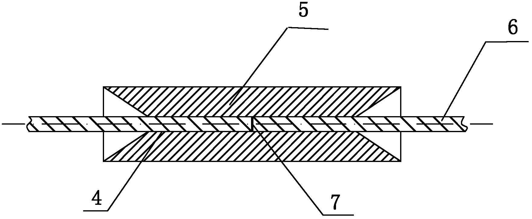
[0035] Such as figure 1 , figure 2 with image 3 As shown, a fiber optic connector includes an alignment tube 5 made of a memory alloy material. The two ends of the alignment tube 5 are tapered optical fiber 6 inlets, and the initial inner diameter of the inner hole of the alignment tube 5 is D. T1 Inner diameter D after low temperature expansion T2 The relationship with fiber 6 is:

[0036] [1-(1-S)×K]×D F T1 F (1)

[0037] D. F T2 F ×(1+S×K) (2)

[0038] D. F is the outer diameter of the optical fiber at the time of docking, K is the shape memory gauge factor of the alignment tube 5 made of memory alloy material, S is a selected proportional coefficient, the preferred K value is 8%, and the S value is selected as 0.5, which also includes thermal shrinkage The sleeve 10, inside the heat-shrinkable sleeve 10 is arranged a heat-melt pipe 12 and a reinforcement 11 located outside the heat-melt pipe 12 and parallel to the heat-melt pipe 12, and the alignment pipe 5 ...

Embodiment 2

[0049] Such as Figure 4 , Figure 5 As shown, in this embodiment, the difference from Embodiment 1 is that the alignment pipe 5 includes a circular pipe 1 in the middle and a semicircular pipe 2 extending to both sides with a radial opening not less than 120 degrees. and semicircular tube II 3. In this way, the first semicircular tube 2 and the second semicircular tube 3 can protect the uncoated bare optical fiber 6 and have good strength when the thermal fusion tube 12 is melted and cooled.

[0050] Preferably, the alignment tube 5 includes a circular tube 1 in the middle and flat plates extending to both sides.

[0051] In this embodiment, the structures, connections and working principles of other parts are the same as those in Embodiment 1.


PUM

PropertyMeasurementUnit
Thicknessaaaaaaaaaa

Abstract

The invention discloses an optical fiber splicer which comprises an alignment tube composed of a memory alloy material. Two ends of the alignment tube are conic optical fiber introduction port. The relationships of the initial inner diameter DT1 of an inner hole of the alignment tube with optical fiber and the inner diameter DT2 of the inner hole of the alignment tube after the alignment tube expands at low temperature with the optical fiber are (1) [1-(1-S)*K]*DF<DT1<DF and (2) DF<DT2<DF*(1+S*K). DF is the outer diameter of the optical fiber when the optical fiber is in abutted connection. K is a shape memory strain coefficient of the alignment tube made of the memory alloy material. S is a selected proportionally coefficient. The optical fiber splicer further comprises a heat-shrinkable sleeve tube. A hot melting tube and a reinforcing piece arranged outside the hot melting tube and parallel to the hot melting tube are arranged inside the heat-shrinkable sleeve tube. The alignment tube is placed on the middle portion inside the hot melting tube. According to the optical fiber splicer, the memory alloy tube is mainly adopted and optical fiber end head connection is performed. The optical fiber splicer has the advantages of being low in cost, easy and convenient to use and good in long-term stability.

Description

technical field [0001] The invention relates to an optical fiber connection device, in particular to an optical fiber connector. Background technique [0002] Optical fiber has been widely used in various regions of the world as a communication line, and it also has great application prospects as a new type of sensing device. Since most of the optical fibers currently used in practice are silica fibers, their core diameters are generally in the range of 4-80 microns, so the requirements for optical fiber joints are very high, such as single-mode optical fibers. The core diameter is generally between 8-10 microns Between two optical fibers, there will be a large loss if the joint deviation of the two optical fibers is one micron. On the other hand, fiber-to-the-home (FTTH for short) is the goal of the next stage of optical fiber communication. In the large-scale application of FTTH, a large number of optical fiber splicing work is required. If the method of fusion splicing m...

Claims


Application Information

Patent Timeline
IPC IPC(8): G02B6/38
Inventor 杜兵
Owner XIAN JINHE OPTICAL TECH
Why Eureka
Try Eureka