Bottle hole reef in frame structure

A frame structure and cave technology, applied in the field of artificial reefs, can solve the problems of difficulty in producing a dense number of caves, no effective caves, and construction costs of fish reefs, and achieve the effects of light weight, small water resistance, and convenient storage and transportation.

Active Publication Date: 2013-06-26
ZHEJIANG OCEAN UNIV
View PDF10 Cites 9 Cited by
  • Summary
  • Abstract
  • Description
  • Claims
  • Application Information

AI Technical Summary

Problems solved by technology

[0004] The invention provides a bottle-hole reef with a good protective frame structure, which can be conven

Method used


Image

  • Bottle hole reef in frame structure
  • Bottle hole reef in frame structure
  • Bottle hole reef in frame structure

Examples


Embodiment 1

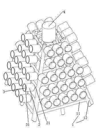
[0024] Embodiment one, see figure 1 , a bottle hole reef with a framework structure, including cave attachments 1 . The cave attachment 1 is a quadrangular truss-shaped frame built with horizontal rods 11 and vertical rods 12 . The horizontal bar material 11 and the vertical bar material 12 are round bars. Horizontal bar material 11 and vertical bar material 12 are the bar (comprising pipe) that abandons. The horizontal bar material 11 and the vertical bar material 12 are made of plastic material. The cave attachment 1 is constructed by a plastic tube.

[0025] Several first plastic bottles 2 are densely covered on the four sides of the cave attachment 1 . The first plastic bottle 2 is a collected waste plastic bottle. The bottleneck 21 of the first plastic bottle has thread (thread is not drawn in the figure). The inner cavity of the first plastic bottle 2 forms a cavity 3 . The bottom of the first plastic bottle 2 is removed so that the bottom end is open. The open b...

Embodiment 2

[0030] Embodiment two, the difference with embodiment one is:

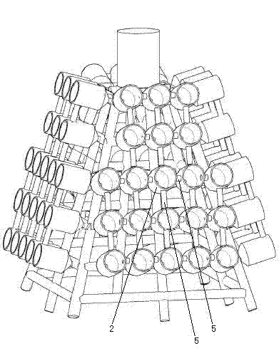
[0031] see image 3 , also includes a number of reinforcing rods 5 . The reinforcing rod 5 is a flexible body. The reinforcing rods 5 are staggered into a network structure. The first plastic bottle 2 is fixed on the nodes between the reinforcing rods. The first plastic bottle 2 is connected with a first float (the first float is fixed inside the first plastic bottle, not shown in the figure). The first float can float the first plastic bottle 2 .

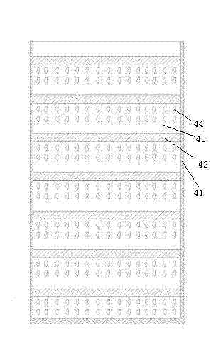
[0032] see Figure 4 , the reinforcing rod 5 is provided with a sealing cavity 51 extending along the length direction of the reinforcing rod, and the sealing cavity 51 is filled with gas. Reinforcing bar 5 can rely on the buoyancy that self suffers to float.

Embodiment 3

[0033] Embodiment three, the difference with embodiment two is:

[0034] see Figure 5 , also includes a connecting rod 7 passing through the mouth 21 of the first plastic bottle and connected to the cave attachment 1. The connecting rod 7 is provided with a first threaded sleeve 71 and a second threaded sleeve 72 . The free end of the connecting rod 7 is provided with threads. Both the first threaded sleeve 71 and the connecting rod 7 are provided with alignable through holes on one end of the cave attachment. The first threaded sleeve 71 is sheathed on the connecting rod 7 and fixed together with the connecting rod 7 after passing through the through hole through the cable tie 9 . The first plastic bottle 2 is screwed on the first threaded sleeve 71 . The first float 6 is fixed on the inner surface of the first plastic bottle 2 .

[0035] The second threaded sleeve 72 is screwed on the free end of the connecting rod 7 . The second plastic bottle 8 is screwed on the sec...


PUM


Abstract

The invention relates to an artificial reef. A bottle hole reef in a frame structure comprises a hole attachment body and a plurality of first plastic bottles, wherein bottle openings of the first plastic bottles are provided with threads, and bottle bottoms of the first plastic bottles are removed. The hole attachment body is a prism-frustum-shaped frame formed by rods, the first plastic bottles are in threaded connection with the hole attachment body through the threads on the bottle openings, the bottom ends of the first plastic bottles incline upwards, inner cavities of the first plastic bottle form a hole, and the open bottom ends of the first plastic bottles form a hole opening. The bottle hole reef in the frame structure can be conveniently manufactured through utilization of wastes and is convenient to recover and good in protective performance, and the problems that an existing fish reef wastes effective resources, no effective holes exist, or holes in dense quantity are hard to manufacture, recovery is not convenient, and stability is poor are solved.

Description

technical field [0001] The invention relates to an artificial reef, in particular to a bottle hole reef with a frame structure. Background technique [0002] For the structures set up in the sea, improve the ecological environment of the sea area, create a good environment for marine organisms to inhabit, provide places for fish to reproduce, grow, bait and shelter enemies, and achieve the purpose of protection, multiplication and increase in catches. The method of putting artificial reefs in waters is usually adopted. [0003] A kind of artificial fish reef is disclosed in the patent document that the Chinese patent application number is 2011103469934, the publication date is July 25, 2012, and the title is "square combined artificial fish reef". Existing fish reefs are all steel frame structures or reinforced concrete structures. There are generally the following deficiencies: poor stability, no real caves or difficult to make a dense number of caves, all of which ar...

Claims


Application Information

Patent Timeline
IPC IPC(8): A01K61/00
CPCY02A40/81
Inventor 宋伟华
Owner ZHEJIANG OCEAN UNIV
Why Eureka
Try Eureka