Method for operating resistor welding apparatus

A technology of resistance welding and triggering device, applied in welding monitoring device, welding power source, welding power source, etc., can solve problems such as high power loss, and achieve the effect of reducing power loss, improving system performance, and uniform magnetization

Active Publication Date: 2013-06-26
ROBERT BOSCH GMBH
View PDF5 Cites 5 Cited by
  • Summary
  • Abstract
  • Description
  • Claims
  • Application Information

AI Technical Summary

Problems solved by technology

[0003] The use of diode rectifiers has the disadvantage that higher power losses occur due to the on-resistance of the diodes

Method used


Image

  • Method for operating resistor welding apparatus
  • Method for operating resistor welding apparatus
  • Method for operating resistor welding apparatus

Examples


Embodiment Construction

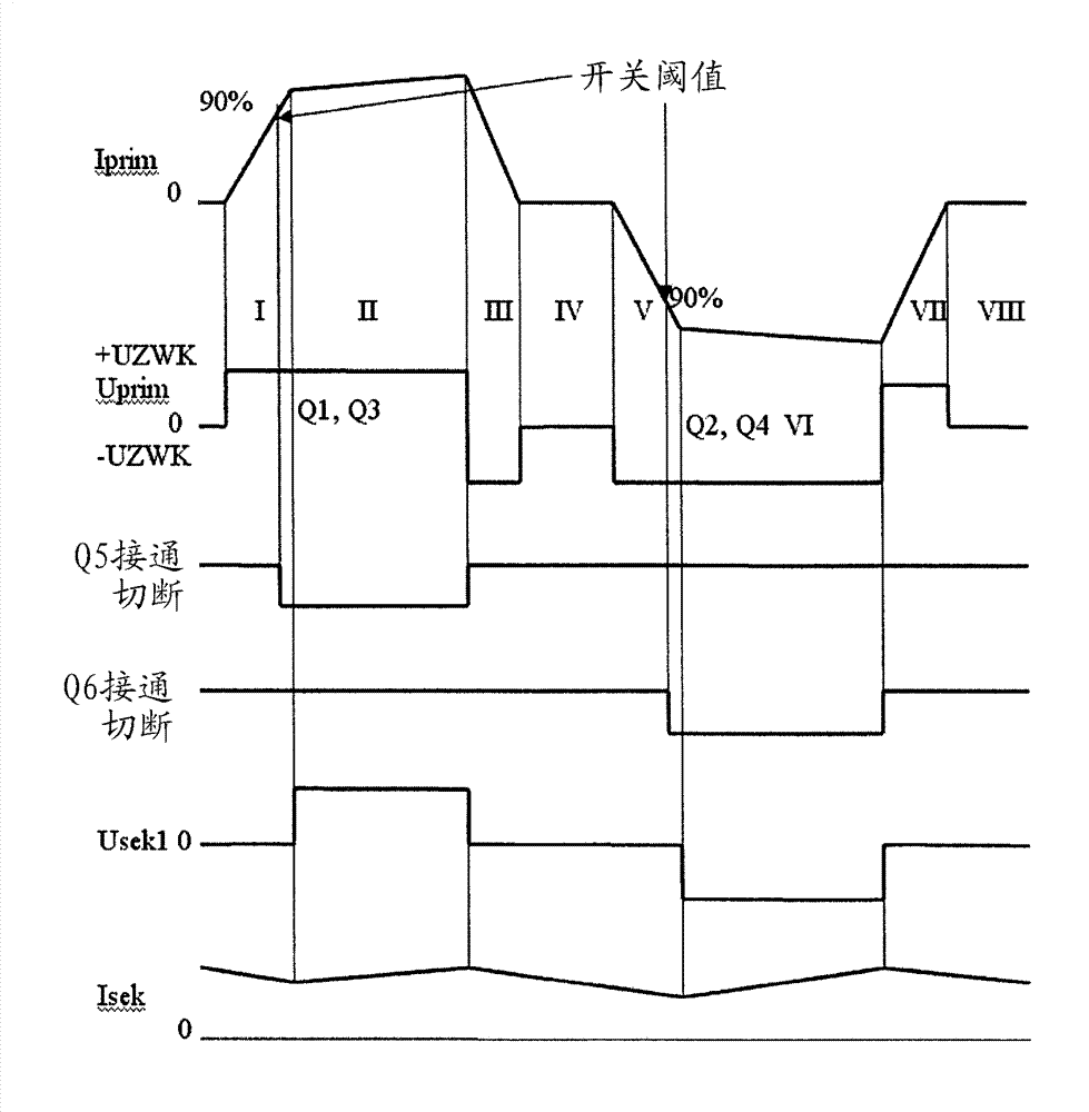
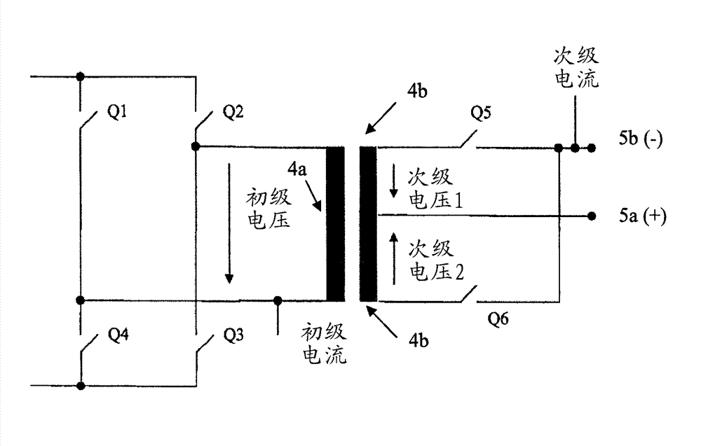
[0029] Figure 1 shows a full bridge together with a synchronous rectifier. Both are installed in resistance welding equipment (not shown).

[0030] The full bridge is shown on the left and comprises two bridge arms. The two bridge arms are at a DC voltage (not shown). Each bridge arm includes two switches Q1 , Q4 and Q2 , Q3 in the form of IGBTs. The IGBTs are triggered by means of pulse trains. In the bridge arm of the device there is the primary winding 4a of the welding transformer. The synchronous rectifier is shown on the right side of FIG. 1 . This synchronous rectifier comprises the two secondary windings 4b and 4c of said welding transformer. The two windings 4b, c are connected in series and have a center tap. In such an embodiment, the corresponding welding electrode 5 a is connected to the center tap, which welding electrode should have a positive potential (+) during the welding process. In this exemplary embodiment (positive potential at the center tap), th...


PUM


Abstract

The invention relates to a method for operating a resistor welding apparatus. The power transmission manner on the resistor welding apparatus is not the optimum manner. The invention relates to the resistor welding apparatus with a welding transformer, the welding transformer includes first and second secondary windings which are coupled with each other, a primary winding and a synchronous rectifier. The operating resistor welding apparatus runs following a specific method, and power transmission is optimized on the system layer in the method.

Description

technical field [0001] The invention describes a method for operating a resistance welding device and a resistance welding device as such a resistance welding device according to the independent claims. Background technique [0002] In resistance welding with direct current, very high currents, possibly in the range of several thousand amperes, are required. To generate these currents, transformers are usually used which are activated on the primary side by means of a full bridge and which supply current to the welding tongs on the secondary side by means of diode rectifiers. [0003] The use of diode rectifiers has the disadvantage that higher power losses occur due to the conduction resistance of the diodes. Contents of the invention [0004] The object of the present invention is to specify a resistance welding device and a method for operating such a resistance welding device, by means of which method the system performance of the entire device is significantly improv...

Claims


Application Information

Patent Timeline
Patent Type & Authority Applications(China)
IPC IPC(8): B23K11/24H02M7/12
CPCB23K11/241B23K11/25H02M3/33592Y02B70/10Y02P70/10
Inventor R.肖尔茨
Owner ROBERT BOSCH GMBH
Why Eureka
Try Eureka