
Magnetron sputtering apparatus and process

A magnetron sputtering and equipment technology, applied in the field of magnetron sputtering equipment, can solve the problems of increasing the manufacturing cost and operating cost of the magnetron sputtering equipment, increasing the complexity of the reaction chamber 3, increasing the volume of the reaction chamber 3, etc. , to achieve the effect of shortening the vacuuming time, simplifying the structure and reducing the production cost

Active Publication Date: 2013-06-26
BEIJING NAURA MICROELECTRONICS EQUIP CO LTD
View PDF2 Cites 10 Cited by
  • Summary
  • Abstract
  • Description
  • Claims
  • Application Information

AI Technical Summary

Problems solved by technology

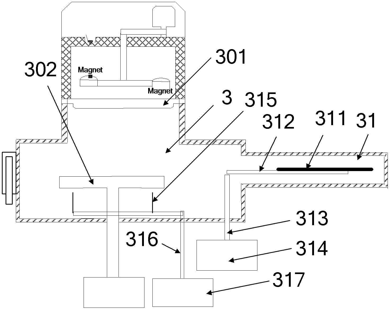
[0006] In the existing magnetron sputtering equipment, the shielding unit is arranged in the reaction chamber 3. Due to its large volume, it needs to occupy a large space, which not only increases the volume of the reaction chamber 3, but also increases the size of the reaction chamber. 3, resulting in an increase in the manufacturing cost and operating cost of the magnetron sputtering equipment

Method used


Image

  • Magnetron sputtering apparatus and process
  • Magnetron sputtering apparatus and process
  • Magnetron sputtering apparatus and process

Examples


Embodiment 1

[0030] Figure 5a It is a cross-sectional view of the loading and unloading chamber in the magnetron sputtering device according to Embodiment 1 of the present invention. Figure 5b for along Figure 5a Sectional view of line A-A in middle. Please also refer to Figure 5a and Figure 5b , the loading and unloading chamber 1 is provided with a carrying device for holding the processed workpiece 4 and the shielding plate 311 and a carrying device lifting mechanism for adjusting the height of the carrying device. A second gate valve 62 communicating with the transfer chamber 2 is provided on the chamber wall of the loading and unloading chamber 1 .

[0031]The carrying device comprises four sub-carriers and a bracket 51 for supporting the carrier, wherein the bracket 51 is vertically arranged, and the four sub-carriers are fixed on the bracket 51 at intervals along the length direction of the bracket 51 (that is, along the vertical direction). , and the carrier board is perp...

Embodiment 2

[0037] In this embodiment, the shielding plate 311 is placed in the transmission chamber 2 , that is, the carrying device for containing the shielding plate 311 and the lifting mechanism of the carrying device for adjusting the height of the carrying device are arranged in the transporting chamber 2 . The structural features of the bearing device and the lifting mechanism of the bearing device are the same as those of the first embodiment, and will not be repeated here. In this embodiment, the shielding disk 311 is placed in the transmission chamber 2, and the transmission of the shielding disk 311 is realized by means of a manipulator, such as transferring the shielding disk 311 from the transmission chamber 2 to the electrostatic chuck 302 in the reaction chamber 3 above, or from the electrostatic chuck 302 to the transfer chamber 2 . Placing the shielding disk 311 in the transfer chamber 2 also avoids setting an auxiliary chamber for placing the shielding disk 311 in the re...


PUM


Abstract

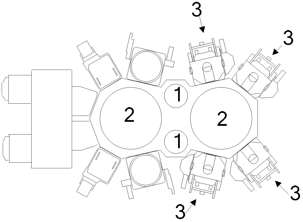
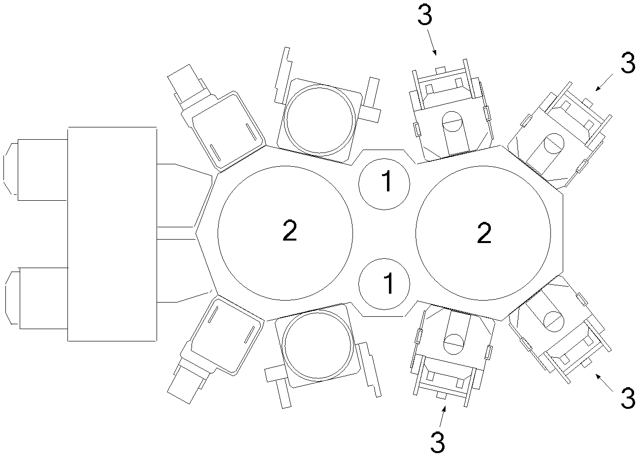
The invention provides a magnetron sputtering apparatus and process. The magnetron sputtering apparatus comprises a loading / unloading chamber, a reaction chamber and a transmission chamber, wherein the loading / unloading chamber is used for loading and unloading a processed workpiece; an electrostatic chuck for supporting the processed workpiece is arranged in the reaction chamber; a mechanical arm for transmitting the processed workpiece between the loading / unloading chamber and the reaction chamber is arranged in the transmission chamber; an obstruction tray for obstructing the surface of the electrostatic chuck is arranged outside the reaction chamber; when the surface of the electrostatic chuck needs to be obstructed, the obstruction tray is transmitted to a position above the electrostatic chuck through the mechanical arm; and when the surface of the electrostatic chuck does not need to be obstructed, the obstruction tray is transmitted from the position above the electrostatic chuck to the outside of the reaction chamber through the mechanical arm. Thus, the invention reduces the volume of the reaction chamber, simplifies the structure of the magnetron sputtering apparatus and lowers the manufacturing cost of the magnetron sputtering apparatus.

Description

technical field [0001] The invention relates to the technical field of microelectronic processing, in particular to a magnetron sputtering device and a process method thereof. Background technique [0002] Magnetron sputtering is to excite the plasma in a high-vacuum reaction chamber, and then use the positive ions in the plasma to bombard the target to sputter out the target atoms and deposit the target atoms on the silicon wafer and other processed workpieces. superior. In practical applications, due to the high purity of the target, it is easy to form a layer of oxide on its surface, which will have a negative impact on the deposition process of magnetron sputtering. Therefore, it is necessary to remove the oxide on the surface of the target before performing the deposition process. [0003] The sputtering method is currently a common method for removing oxides on the target surface. During the process of removing oxides, the removed oxides are likely to fall on the su...

Claims


Application Information

Patent Timeline
Patent Type & Authority Applications(China)
IPC IPC(8): C23C14/35C23C14/50
Inventor 夏威王厚工宗令蓓窦润江陈春伟
Owner BEIJING NAURA MICROELECTRONICS EQUIP CO LTD
Learn More