

Multidirectional corrugated inner finned tube
A technology of corrugated fins and inner fins is applied in the field of strengthening heat transfer and heat exchange tubes, which can solve the problems of rare ways of strengthening heat transfer, and achieve the effects of inhibiting scaling in the tube, strengthening heat transfer, and being easy to manufacture and process.
- Summary
- Abstract
- Description
- Claims
- Application Information
AI Technical Summary
Problems solved by technology
Method used
Image

Examples
Embodiment 1
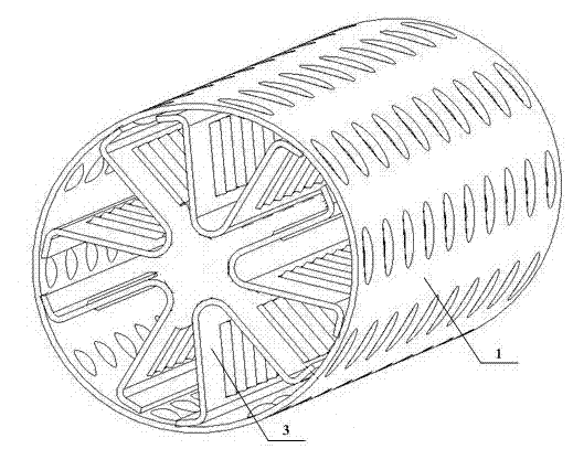
[0055] Such as figure 1 and Figure 4 As shown, the present invention includes an outer tube 1, and a plurality of multidirectional corrugated inner fins 3 are evenly distributed on the inner peripheral surface of the outer tube 1, and the multidirectional corrugated inner fins 3 include a root 4, two straight walls 5 and two Bending 6, multi-directional corrugations 7 are distributed on the two straight walls 5, and the trend of the lines of the multi-directional corrugations 7 on the same straight wall is consistent. The bending 6 is brazed with the inner surface of the outer tube 1, and the straight walls 5 are 1 extends radially, and the outer tube 1 and the multi-directional corrugated inner fins 3 form multiple parallel flow channels.
Embodiment 2
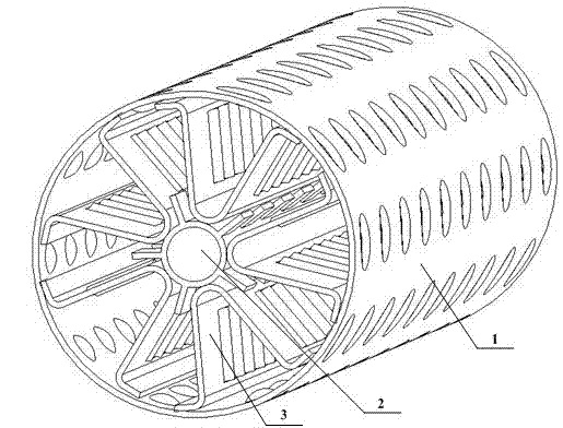
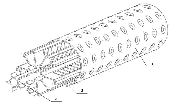
[0057] Such as figure 2 , image 3 and Figure 4 As shown, as an improvement of the present invention, the multi-directional corrugated inner finned tube of the present invention also includes a core tube 2, the core tube 2 is concentrically nested with the outer tube 1, and the tube central axes of the outer tube 1 and the core tube 2 coincide The root 4 of the multi-directional corrugated inner fin 3 is brazed with the outer surface of the core tube 2, and the core tube 2 and multiple multi-directional corrugated inner fins 3 divide the outer tube 1 into several independent parallel flow channels. The core tube 2 serves as a supporting body and becomes a component of the entire multi-directional corrugated inner fin tube, which can enhance the structural strength of the multi-directional corrugated inner fin 3, increase the effective heat transfer area and conduct flow.
[0058] Such as Figure 4 , Figure 5 and Figure 6 As shown, the multi-directional corrugated inne...
PUM
 Abstract
Description
Claims
Application Information