Monitoring for settlement of railroad bed
A railway roadbed and roadbed technology, applied in the direction of hydrostatic pressure, etc., can solve the problems of monitoring railway settlement, etc., and achieve the effect of strong adaptability, simple structure and good repeatability
- Summary
- Abstract
- Description
- Claims
- Application Information
AI Technical Summary
Problems solved by technology
Method used
Image
Examples
Embodiment 1
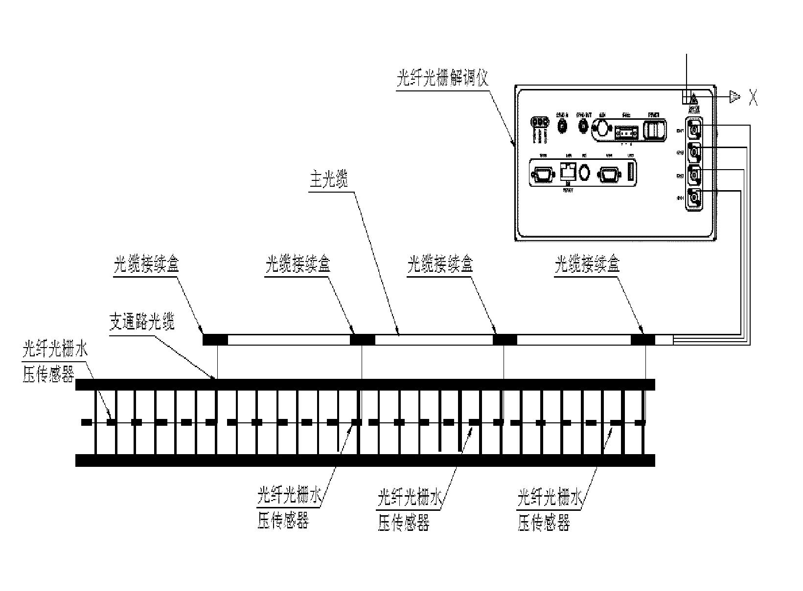
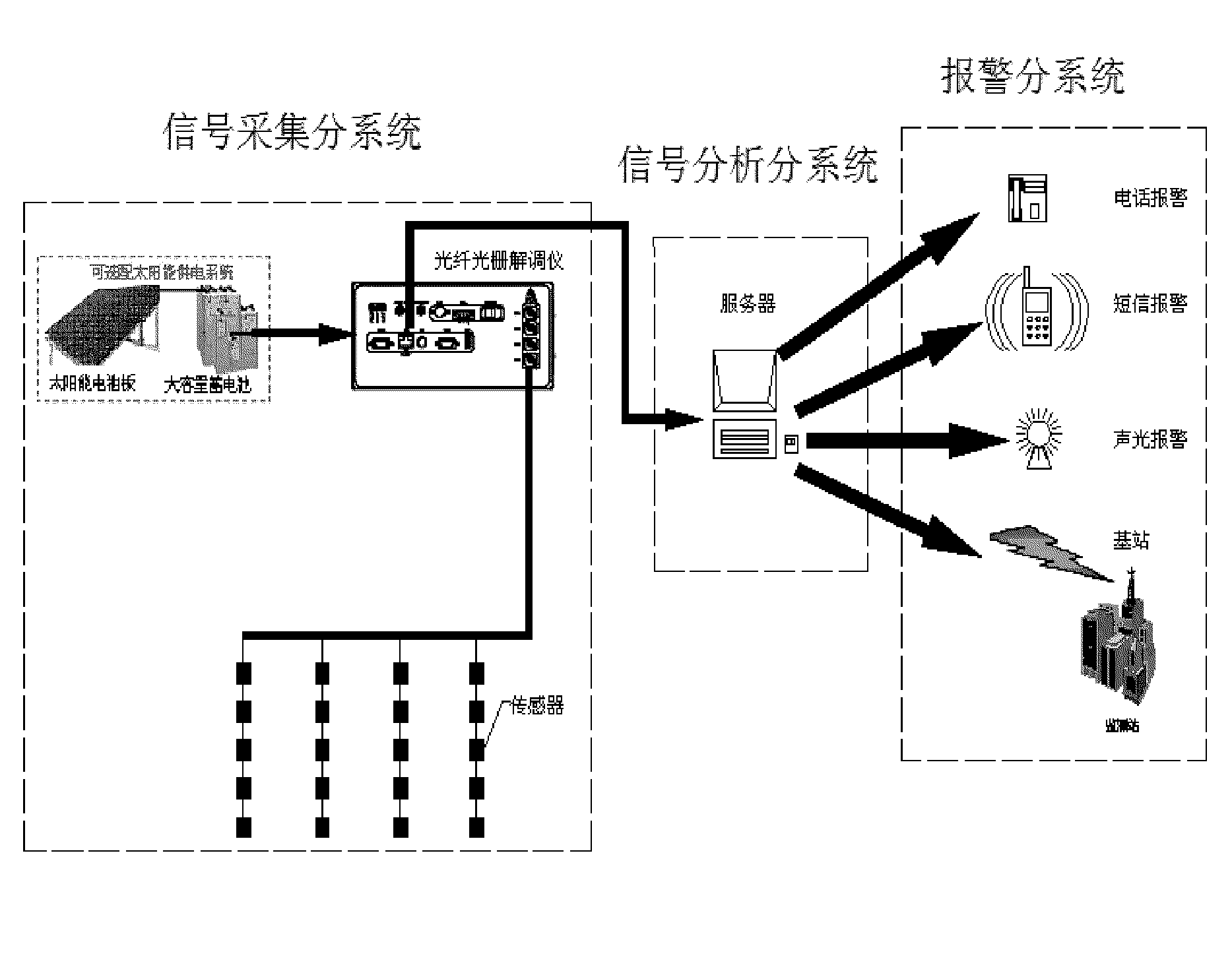
[0030] According to the signal acquisition subsystem shown in Embodiment 1, through water pressure monitoring, it mainly includes a water tank and a water channel laid on site, an optical fiber grating sensor, an optical fiber network, and an optical fiber grating demodulator.
[0031]As shown in Figure 2 and Figure 3, the basic principle of the information collection subsystem is: by laying soft water pipes under the railway subgrade, and installing fiber optic grating sensors on the top of the water pipes to detect the water pressure changes of the corresponding pipelines. When settlement occurs, the pipeline will sink with the settlement, and its position change will cause the water pressure measured by the sensor to change. The grating fiber optic sensor senses the settlement by detecting the change of water pressure in the pipeline.
[0032] Wherein, the water pipe and the sensor are generally arranged in a suitable layer in the subgrade, such as a sandy soil filling layer...
Embodiment 2
[0049] According to Embodiment 2, another acquisition subsystem for collecting settlement information includes: installing an optical fiber grating sensor for measuring pressure changes in the settlement layer of the roadbed.
[0050] Wherein, the railway embankment can generally be divided into several layers, and each layer is covered with the upper layer after compaction. Generally, there are one or several layers prone to subsidence. Specifically, a pre-set plate is set at a certain position on the top of the layer that is prone to settlement, which separates the layer that is easy to settle (such as sand and soil landfill) and the non-settling layer (such as stone filling or cement pouring layer), and the lower surface can be A fiber grating pressure sensor is provided for measuring the pressure exerted by the sensed sedimentation layer on it. In the case of subsidence, the pressure it measures decreases until it reaches zero. In this way, the subsidence situation at a ...
Embodiment 3
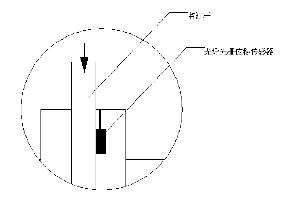
[0057] According to Embodiment 3, another information collection and analysis system is proposed, including: setting an optical fiber grating sensor structure for measuring relative displacement in the subsidence layer of the roadbed. Specifically, as shown in Figures 6a and 6b, a sleeve and a pole are set at each position, wherein the sleeve is relatively fixed due to friction with each layer, and the pole moves downward with the settlement of the sedimentation layer. A fiber grating displacement sensor is arranged at a certain position of the casing or the pole. By measuring the relative displacement between the casing and the pole, it is possible to measure whether and how much settlement has occurred.
[0058] The signal acquisition subsystem according to Embodiment 3 can also be represented by FIG. 4 . The information collection subsystem includes: a distributed array of optical fiber grating displacement sensors, optical fiber cables, and optical fiber grating demodulat...
PUM
 Abstract
Description
Claims
Application Information
 - R&D
- Intellectual Property
- Life Sciences
- Materials
- Tech Scout
- Unparalleled Data Quality
- Higher Quality Content
- 60% Fewer Hallucinations
Browse by: Latest US Patents, China's latest patents, Technical Efficacy Thesaurus, Application Domain, Technology Topic, Popular Technical Reports.
© 2025 PatSnap. All rights reserved.Legal|Privacy policy|Modern Slavery Act Transparency Statement|Sitemap|About US| Contact US: help@patsnap.com


