
Direct-current filter inductor and manufacturing method thereof

A technology of DC filtering and manufacturing method, which is applied in the field of inductors, can solve problems such as inconvenience, and achieve the effect of reducing AC loss and facilitating detection

Active Publication Date: 2013-06-26
DELTA ELECTRONICS SHANGHAI CO LTD
View PDF5 Cites 17 Cited by
  • Summary
  • Abstract
  • Description
  • Claims
  • Application Information

AI Technical Summary

Problems solved by technology

[0007] This shows that above-mentioned existing inductor obviously still has inconvenience and defective, and needs to be further improved
In order to solve the above problems, related fields have tried their best to find a solution, but no applicable method has been developed for a long time.

Method used


Image

  • Direct-current filter inductor and manufacturing method thereof
  • Direct-current filter inductor and manufacturing method thereof
  • Direct-current filter inductor and manufacturing method thereof

Examples


Embodiment Construction

[0085] In order to make the technical content disclosed in this application more detailed and complete, reference may be made to the drawings and the following various specific embodiments of the present invention, and the same symbols in the drawings represent the same or similar components. However, those skilled in the art should understand that the examples provided below are not intended to limit the scope of the present invention. In addition, the drawings are only for schematic illustration and are not drawn according to their original scale.

[0086] In this application, the description involving "coupled with" may generally refer to a component being indirectly connected to another component through other components, or a component is directly connected to another component without going through other components. components.

[0087] In this application, "a" and "the" can generally refer to a single or a plurality, unless the article is specifically limited in the co...


PUM


Abstract

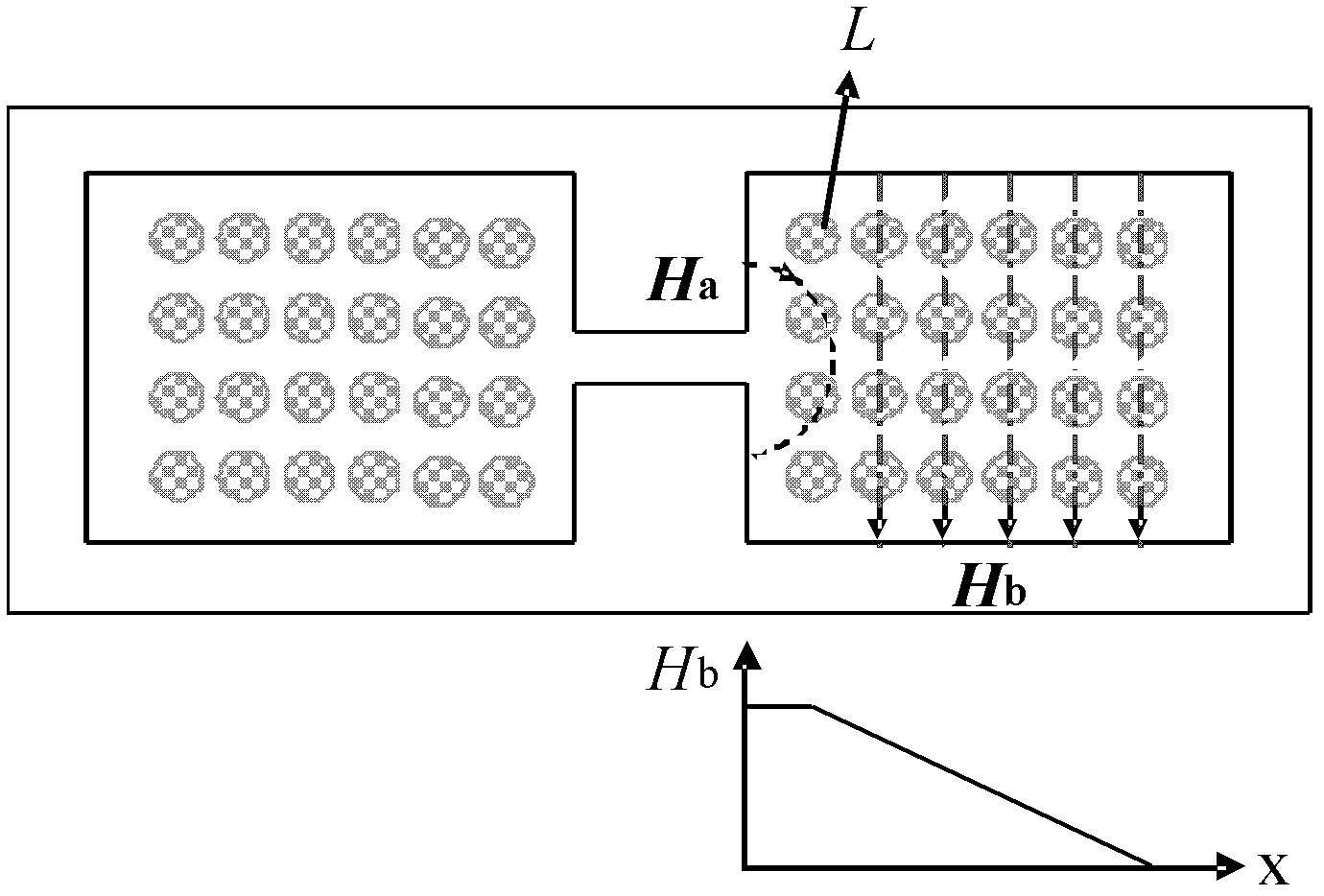
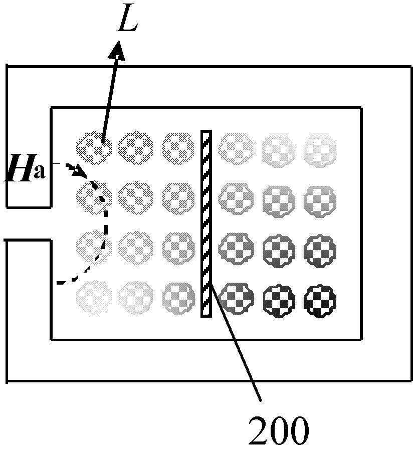
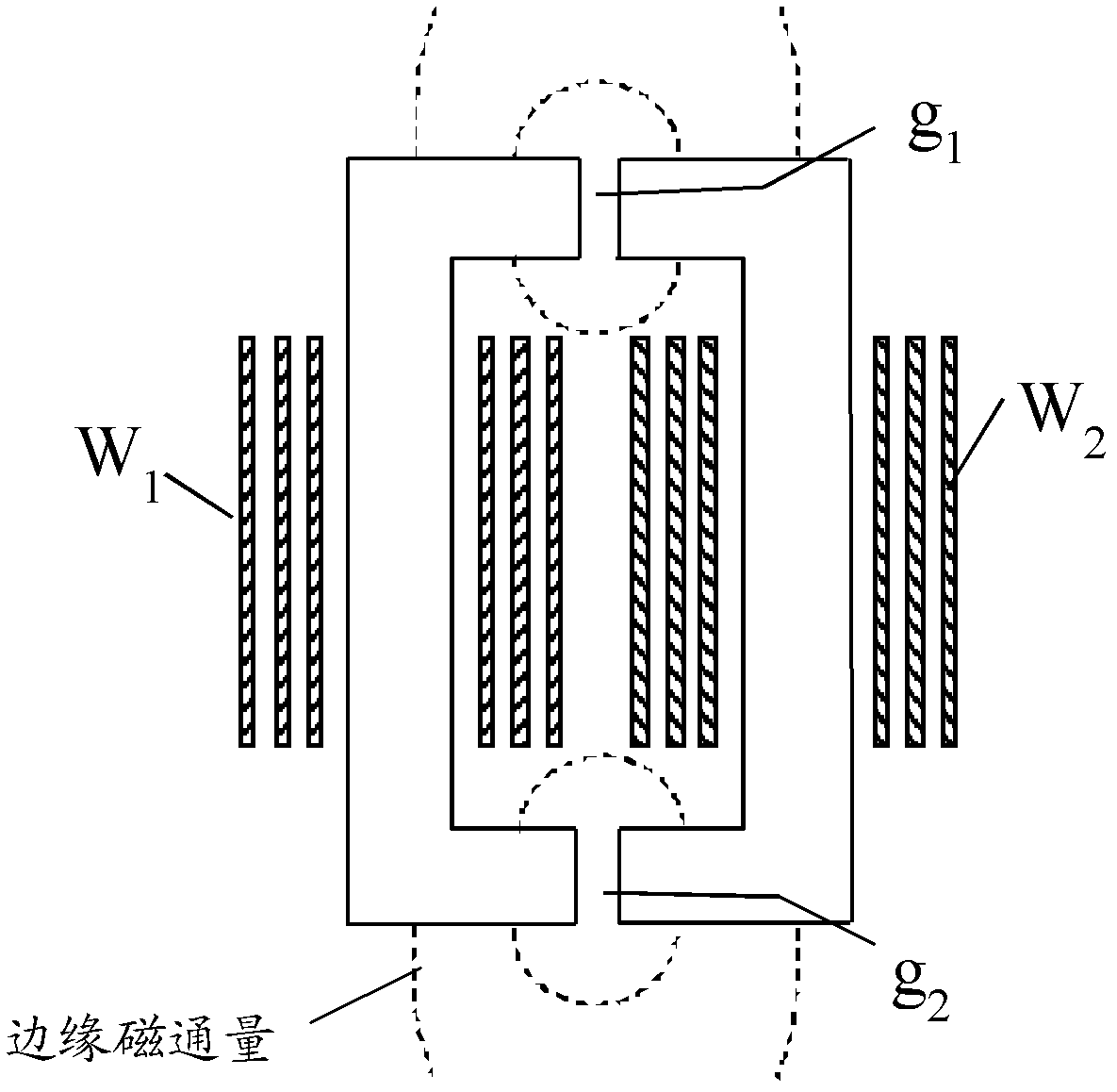
The invention provides a direct-current filter inductor and a manufacturing method thereof. The direct-current filter inductor comprises a magnetic core, at least one first winding and at least one second winding. The magnetic core is provided with at least one air gap. The first winding and the second winding are connected with each other in parallel and are respectively coiled on the magnetic core. The difference value between the inductance value of the first winding and the mutual inductance value of the first winding and the second winding is smaller than the difference value between the inductance value of the second winding and the mutual inductance value of the second winding. The direct current resistance of the first winding is larger than that of the second winding. The first winding is closer to the air gap than the second winding. The direct-current filter inductor is formed by two independent inductive windings which are coiled on the same magnetic column and are connected with each other in parallel, achieves separating of alternate current and direct current of the windings through coupling, and is capable of reducing alternating current loss of the windings, improving magnetic flux distribution near the air gap, and reducing influence of electromagnetic interference.

Description

technical field [0001] The invention relates to an inductor, in particular to a DC filter inductor and a manufacturing method thereof. Background technique [0002] In the case of DC-DC switching power conversion, the switching frequency is more than tens of kHz, and the filter inductor often includes two parts, one is DC current, and the other is high-frequency AC ripple current. In the case of AC-DC switching power conversion, such as an active PFC circuit, the current of the filter inductor is also a low-frequency (<400Hz) AC current (compared to the switching frequency, it can be regarded as a DC current), and the other part is a high-frequency AC ripple. current. Since the inductor contains both DC component current and AC ripple current, this type of inductor is collectively referred to as "DC filter inductor". [0003] The DC current of the DC filter inductor will form a large DC magnetic potential on the magnetic circuit. For inductors made of high magnetic per...

Claims


Application Information

Patent Timeline
IPC IPC(8): H01F17/04H01F27/28H01F27/30H01F27/24H01F41/00
CPCH01F3/14H01F27/28H01F27/38
Inventor 卢增艺
Owner DELTA ELECTRONICS SHANGHAI CO LTD
Learn More