White-light light emitting diode (LED) light-emitting device directly driven by alternating current
A light-emitting device and alternating current technology, which is applied in the direction of electric light source, lighting device, electric lamp circuit layout, etc., can solve the problems of AC voltage light flickering, damage to LED devices, driving current fluctuations, etc., and overcome the phenomenon of LED flickering , Reduce power loss and improve efficiency
- Summary
- Abstract
- Description
- Claims
- Application Information
AI Technical Summary
Problems solved by technology
Method used
Image
Examples
Embodiment 1
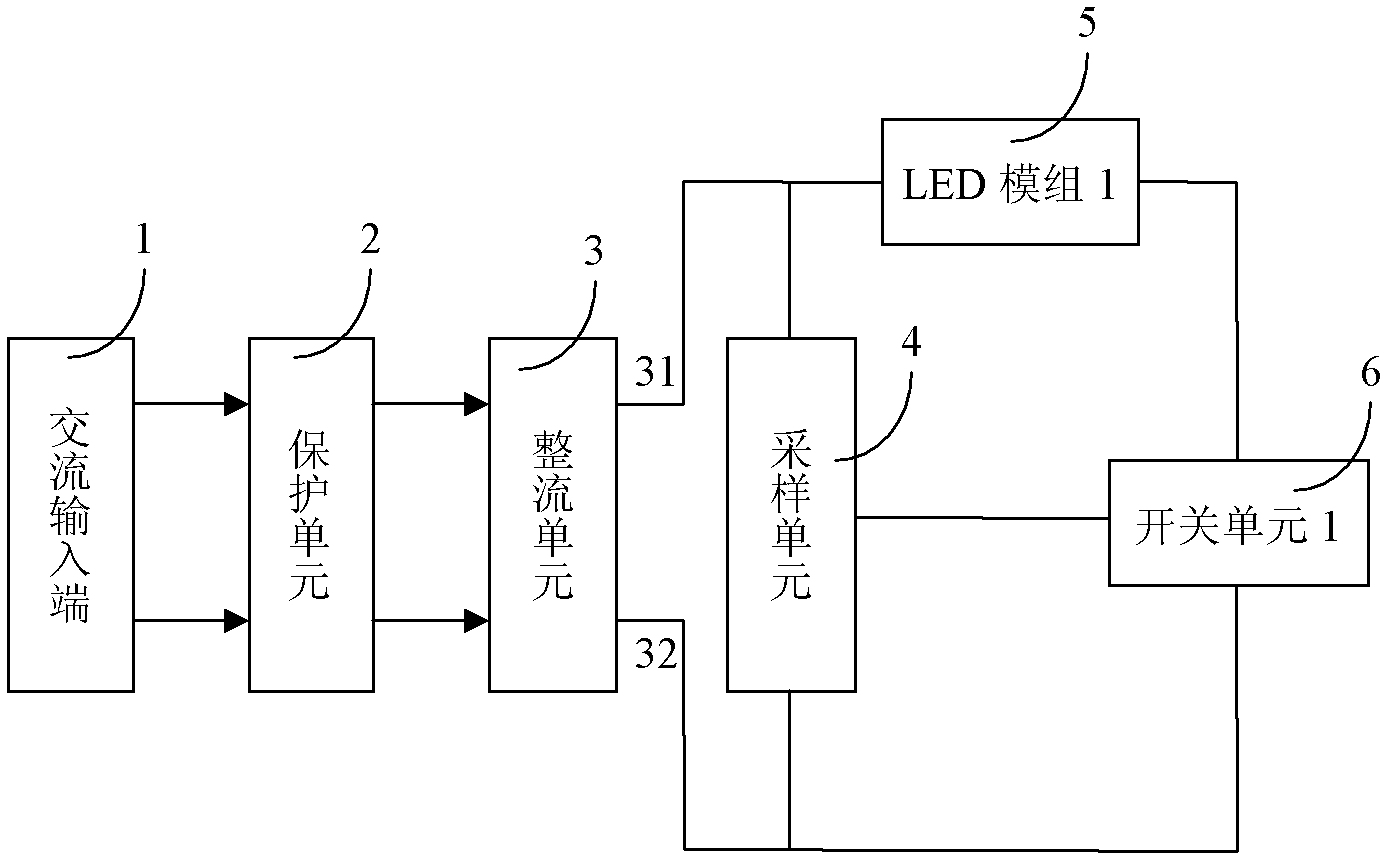
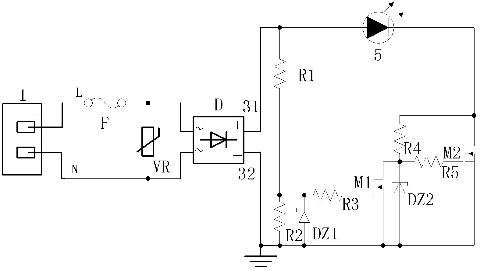
[0049] see figure 1 and figure 2 , the lighting device in this example includes an AC input terminal 1, a protection unit 2, a rectification unit 3, a sampling unit 4, a switch unit 6 and an LED module 5, and the number of LED modules 5 in this example is 1 (ie n=1). The first output terminal of the rectifier unit in this example is a positive DC output terminal 31 , and the positive terminal 31 is connected to the second output terminal DC output negative terminal 32 through the switch unit 6 of the LED module 5 . see figure 1 . The AC input terminal 1 is connected to the L terminal (phase line) and the N terminal (neutral line) of the AC power, and the AC power is introduced into the protection unit 2 . The protection unit 2 provides the basic protection function for the whole device. It is composed of a varistor VR and a fuse F. The fuse F is connected in series with the phase line, and the varistor is connected in parallel between the phase line and the neutral line. S...
Embodiment 2
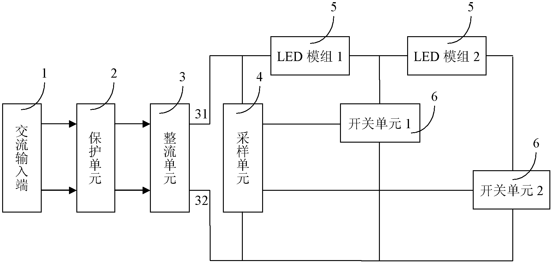
[0055] Such as image 3 As shown, there are 2 LED modules 5 in the light-emitting device of this example, and 2 switch units 6, and the positive terminal 31 of the rectifier unit 3 passes through 2 LED modules and the second switch unit 6 (marked as switch unit 2 in the figure, other The switching unit is labeled similarly) to the negative terminal 32 of the rectifying unit 3, and between the first LED module 5 and the second LED module 5, there is a channel formed by the first switching unit 6 and the negative terminal of the rectifying unit 3 32 connections. In this example, all the switch units 6 are connected to the sampling unit 4 .
Embodiment 3
[0057] Such as Figure 4 As shown, there are three LED modules 5 of the lighting device in this example, and three switch units 6, and the positive terminal 31 of the rectifier unit 3 is connected to the negative terminal 32 of the rectifier unit 3 through three LED modules and the third switch unit 6, Between the first LED module 5 (marked as LED module 1 in the figure, and other LED modules are marked similarly) and the second LED module 5, there is a channel and rectification unit composed of the first switch unit 6 3 negative terminal 32 connection. Between the second LED module 5 and the third LED module 5 , there is a channel formed by a second switch unit 6 connected to the negative terminal 32 of the rectifier unit 3 . In this example, all the switch units 6 are connected to the sampling unit 4 .
[0058] The circuit schematic diagram of the device in this example is shown in Figure 5 As shown, its working principle and specific circuit structure are similar to tho...
PUM
 Abstract
Description
Claims
Application Information
 - R&D
- Intellectual Property
- Life Sciences
- Materials
- Tech Scout
- Unparalleled Data Quality
- Higher Quality Content
- 60% Fewer Hallucinations
Browse by: Latest US Patents, China's latest patents, Technical Efficacy Thesaurus, Application Domain, Technology Topic, Popular Technical Reports.
© 2025 PatSnap. All rights reserved.Legal|Privacy policy|Modern Slavery Act Transparency Statement|Sitemap|About US| Contact US: help@patsnap.com


