Double-acting lockwasher

A gasket and support element technology, applied in the field of locking gaskets, can solve problems such as nut locking failure, and achieve the effect of improving fatigue strength

Active Publication Date: 2013-07-03
NORD LOCK INT
View PDF9 Cites 7 Cited by
  • Summary
  • Abstract
  • Description
  • Claims
  • Application Information

AI Technical Summary

Problems solved by technology

Therefore, the lock

Method used


Image

  • Double-acting lockwasher

Examples


Embodiment Construction

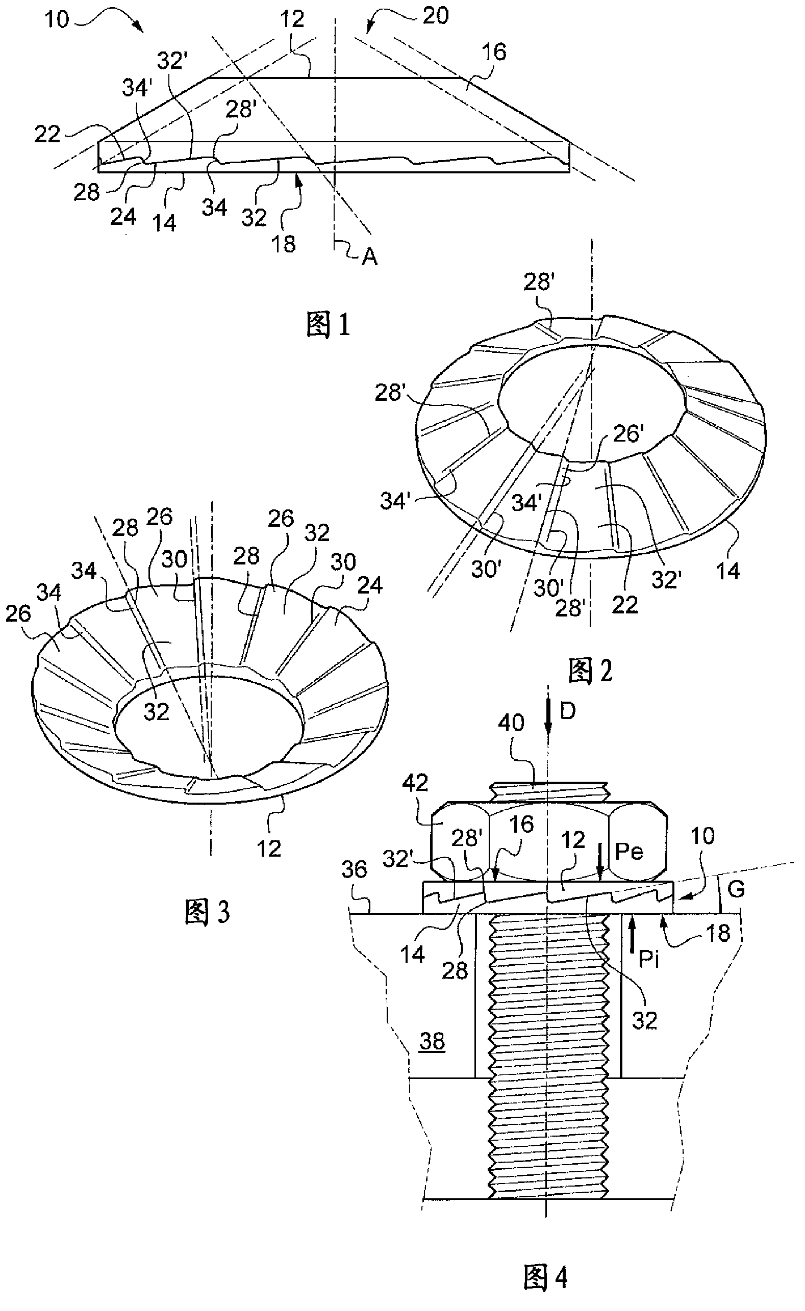
[0027] figure 1 A frustoconical locking washer 10 with an axis of symmetry A is shown in section. The figure shows the outer crown 12 and the inner crown 14 on the inside. The two rings 12, 14 engage each other and will be explained in detail below. Outer ring crown 12 has outer bearing journal 16 and infigure 1 The inner bearing journal 18 is shaded in the middle, while the locking washer 10 has a circular central hole 20 which can eg be engaged to a screw rod.

[0028] now refer to figure 2 , 3 . figure 2 represents a top perspective view of the inner crown 14, and figure 2 The outer ring crown 12 looking up appears. The outer crown 12 forms a first intermediate cone, while the inner crown 14 forms a second intermediate cone. The inner crown 14 has a convex joint surface 22 and the outer crown 12 has a concave joint surface 24 . The two joining surfaces 22 , 24 are complementary and can join each other, leaving no free space between the two rings 14 , 12 . The tw...


PUM


Abstract

The invention relates to a lockwasher which is to be inserted between a bearing element (38) and a screwable element (42), and which includes two rings (12, 14), each of which have an engagement surface (24, 22). Said rings (12, 13), which engage with one another and maintained compressed under axial pressure between said screwable element (42) and said bearing element (38), are capable, when said screwable element is unscrewed, of rotatably engaging with said screwable element (42) and said bearing element (38), respectively, so as to rotate said rings (12, 14) relative to one another, in order to rotatably lock said screwable element (42). According to the invention, said lockwasher (10) is frusto-conical, and said lockwasher (10) is elastically deformable in order to be able to be flattened, forming a spring such that said axial pressure is maintained substantially constant.

Description

technical field [0001] The present invention relates to a locking washer that enables a screw / nut system to be held against rotation after tightening. Background technique [0002] For example known locking washers are formed from a substantially deformed elastic stub ring such that the two free ends of the ring form a point. The ring is then used, for example, to engage between the support element and the nut, while the screw extends beyond the crown of the support element and through the elastic ring. When the nut is tightened, the elastic ring is crushed between the supporting element and the nut, and the ring tips are respectively inserted therebetween to form a brake. [0003] The locking washers are simpler, but they are only so-so. [0004] Other more complex locking washers comprise two rings which engage coaxially with each other and which can be engaged between the support element and the nut. Each of them has a joint face and a ribbed opposing joint face. The ...

Claims


Application Information

Patent Timeline
IPC IPC(8): F16B39/24F16B39/282
CPCF16B39/24F16B39/282F16B39/00F16B43/00
Inventor 克里斯托夫·戴查尔
Owner NORD LOCK INT
Why Eureka
Try Eureka