Combined cutting tool for processing finned tube

A technology of finned tubes and cutters, which is applied in the field of improvement of cutter combinations, can solve the problems of high weight per unit length of finned tubes, high cutter cost, and low fin height, etc., and achieve thinner fin thickness, lower cutter cost, The effect of reducing mold change time

Active Publication Date: 2013-07-10
GOLDEN DRAGON PRECISE COPPER TUBE GROUP
View PDF8 Cites 7 Cited by
  • Summary
  • Abstract
  • Description
  • Claims
  • Application Information

AI Technical Summary

Problems solved by technology

The disadvantages are: higher tool cost, higher weight per unit length of finned tubes, and relatively low fin height
The disadvantage is that the stability during processing is poor, especially if you want to thin the fins only by thinning the gasket, but due to the metal fluidity and complex mechanics of metal processing, if you blindly thin the gasket There will be unstable phenomena such as fin thinning but low fin height or fin rot

Method used


Image

  • Combined cutting tool for processing finned tube
  • Combined cutting tool for processing finned tube
  • Combined cutting tool for processing finned tube

Examples


Embodiment 1

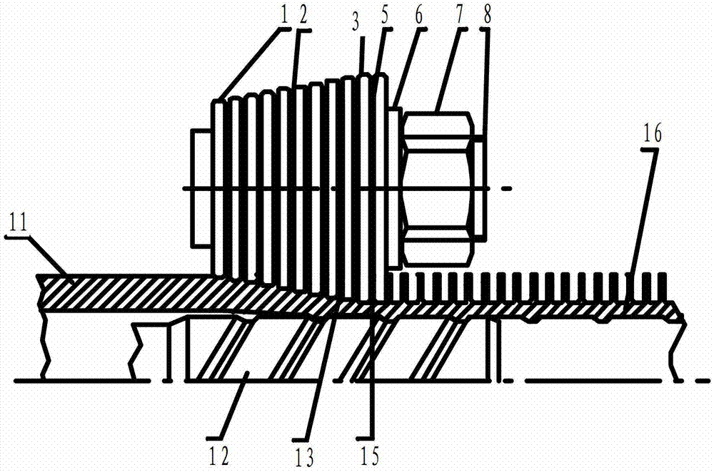
[0036] Embodiment one, such as Figure 4 As shown, according to the present embodiment, the tool for processing finned tubes and its combination include a main shaft 8, a transition blade 1 fixedly sleeved on the main shaft 8 from left to right, a transition spacer 2 clamped in the middle of the transition blade, and a row of Positioning washer 4 at the position behind transitional blade 1, shaped blade 3, shaped washer 5, washer 6 and nut 7 for locking and fixing the blade.

[0037]In this embodiment, a combination of unsharpened blades plus gaskets and unsharpened blades of different thicknesses plus gaskets of different thicknesses is used. The thickness of the transition blade 1 is 0.4 mm. There are 9 transition blades from left to right. The diameters are 65.4mm, 65.6mm, 65.8mm, 66mm, 66.2mm, 66.4mm, 66.6mm, 66.8mm, 67mm. In the middle of the transition blade 1 are 8 transition gaskets 2 with a thickness of 0.25 mm and an outer diameter of 64 mm. The combination of the ...

Embodiment 2

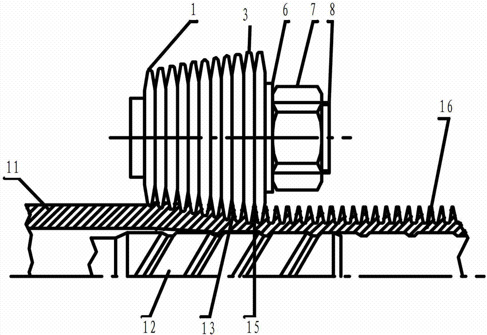
[0038] Embodiment two, this embodiment adopts prior art such as figure 2 Shown: the combination of prior art using transition blade 1 and transition spacer 2. The thickness of the transition blade 1 is 0.45mm, and the outer diameter from left to right is 65.4mm, 65.6mm, 65.8mm, 66mm, 66.2mm, 66.4mm, 66.6mm, 66.8mm, 67mm, a total of 9 pieces, and the thickness of the shaping blade 3 is 0.45mm mm, with an outer diameter of 67.1mm, a total of 2 pieces; a transition gasket 2 with a thickness of 0.1mm and an outer diameter of 64mm, a total of 9 pieces, and a shaped gasket 5 with a thickness of 0.1mm and an outer diameter of 64mm, a total of 1 piece. In this embodiment, the maximum height of the shaped fins 15 processed during the processing test is 0.7mm, and the thickness of the fins is 0.12mm. Wings, poor surface, rotten wings, excessive vibration and other unstable phenomena. After this embodiment, the technology of the present invention is adopted such as image 3 As shown,...

Embodiment 3

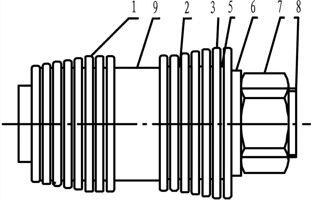
[0040] Embodiment three, this embodiment adopts prior art such as figure 1 Shown: Combination of prior art with transition sharpened insert 1 . The thickness of the transition blade 1 is 0.9mm, and the cutting angle α is 13°. The outer diameters from left to right are 65.4mm, 65.6mm, 65.8mm, 66mm, 66.2mm, 66.4mm, 66.6mm, 66.8mm, 67mm, shaped blades 3 The thickness is 0.9mm, the cutting edge angle α is 13°, and the outer diameter is 67.1mm, a total of 2 pieces; the maximum height of the shaped fin 15 processed in the process of the processing test in this embodiment is 1.5mm, after the test processing section 16 The length is 100000m, and when the average processing section 16 length is 400m, phenomena such as cracking or deformation appear in the shaping blade 3 . Adopt technology of the present invention such as after embodiment Figure 5 As shown, combinations of sharpened blades of different thicknesses are used. The thickness of the transition blade 1 is 0.9mm, and the ...


PUM

PropertyMeasurementUnit
thicknessaaaaaaaaaa
thicknessaaaaaaaaaa
thicknessaaaaaaaaaa

Abstract

The invention discloses a combined cutting tool for processing a finned tube. The combined cutting tool comprises a spindle (8), a transition blade (1), a design-finalized blade (3), a transition gasket (2) clamped in the middle of the transition blade, a design-finalized gasket (5) clamped in the design-finalized blade, a positioning gasket (4) clamped between the transition blade and the design-finalized blade, a gasket (6) and a nut (7), wherein the transition blade (1) and the design-finalized blade (3) are fixedly sleeved on the spindle (8), and the gasket (6) and the nut (7) are used for locking and fixing the blades. The combined cutting tool is characterized in that the transition blade (1) is kept to be invariant, the thickness of the design-finalized blade (3) is larger than that of the transition blade (1), the thickness of a fin is reduced through combining different cutting tools and gaskets, and accordingly the purpose of reducing the weight per unit length of the fin is achieved. The combined cutting tool for processing the finned tube has the advantages that the fin thickness is reduced, the weight per unit length of the fin reduced, and the cost is saved; the fin height and the fin shape before the fin design is finalized are ensured; the stability in the processing process is high; the die replacement time is reduced, and the work efficiency is improved; the gaskets can be used repeatedly; a cutting tool combining and arranging mode is simple, the cutting tool cost is low, and the blade using time is long.

Description

technical field [0001] The invention belongs to the field of mechanical processing, in particular to an improvement of a tool combination for processing finned tubes. Background technique [0002] Heat transfer problems are encountered in many areas of refrigeration and air-conditioning technology and energy technology, where tube-bundle heat exchangers are often used for heat transfer. The key component in the tube bundle heat exchanger, the heat exchange tube, is the core that determines its processing cost and heat exchange efficiency. There are various forms of heat exchange tubes, but finned tubes are currently the most common application. [0003] Finned tubes have been widely used in refrigeration, chemical industry, metallurgy and many other industries as heat exchange and heat dissipation components. The finned tube mainly improves the heat exchange efficiency by increasing the heat conduction area, and the current finned tube is usually made into an overall spira...

Claims


Application Information

Patent Timeline
Patent Type & Authority Applications(China)
IPC IPC(8): B21D37/00B21D15/04B21D53/06
Inventor 常建民王志军武永强王大同李前方张小广
Owner GOLDEN DRAGON PRECISE COPPER TUBE GROUP
Why Eureka
Try Eureka