
Production well resistivity logging device

A technology for resistivity logging and production wells, applied in boreholes/well components, earthwork drilling and production, etc., can solve problems such as difficult logging, low work efficiency, and failure to consider casing degaussing, and improve logging Efficiency, impact reduction effect

Inactive Publication Date: 2013-07-10
XI'AN PETROLEUM UNIVERSITY
View PDF6 Cites 4 Cited by
  • Summary
  • Abstract
  • Description
  • Claims
  • Application Information

AI Technical Summary

Problems solved by technology

The main problem of this type of instrument is: since the conductivity of the casing itself is several orders of magnitude larger than that of the formation, when the emitter electrode is applied to the formation through the electrode in contact with the casing, most of the current is consumed on the casing , only a small part of the current flows into the formation, coupled with the influence of various factors such as the corrosion of the casing, the cement quality outside the casing, and the natural potential of the formation itself, the signal-to-noise ratio is very low, and logging is difficult. Since the pushing of the electrode must be in contact with the bushing, it is bound to destroy the wax protection layer of the bushing, and the noise caused by moving the electrode is 10 times larger than the useful signal. 4 Times, in order to reduce the thermal potential and friction potential, the instrument usually adopts point measurement method, and the work efficiency is low
[0005] "Journal of Instrument and Apparatus" 2009 09 paper "Casing Magnetization and Casing Medium Identification" announced a transient electromagnetic logging method in the well, through the magnetization treatment of the casing in the measurement area, the penetration of the transmitted signal in the well is enhanced However, since the magnetizing coil and the transmitting coil are in the same horizontal position, the magnetizing field has a great influence on the detection system, and the extraction and processing of logging signals are complicated
[0006] Chinese patent ZL200920247085.8 discloses an electromagnetic logging device for oilfield production wells. Although the magnetization part and the logging coil system are separated, the demagnetization problem after casing magnetization is not considered. The depth of the magnetic mark is used as the standard depth, and when the residual magnetic intensity of the downhole casing exceeds a certain value, the logging cable will be magnetized, resulting in the inability to identify the magnetic mark, thereby affecting the normal logging operation

Method used


Image

  • Production well resistivity logging device
  • Production well resistivity logging device
  • Production well resistivity logging device

Examples


Embodiment Construction

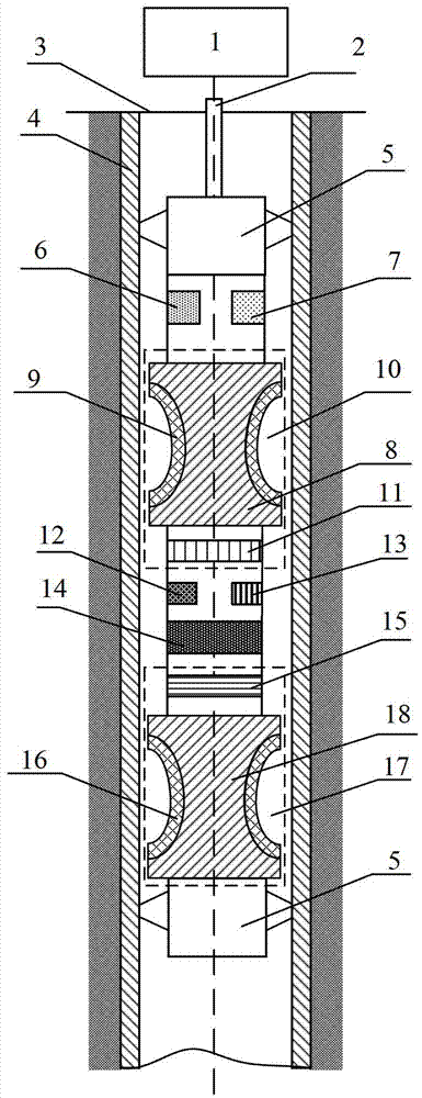
[0023] The structural principle and working principle of the present invention will be described in detail below in conjunction with the accompanying drawings.

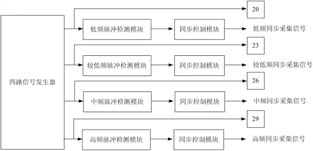
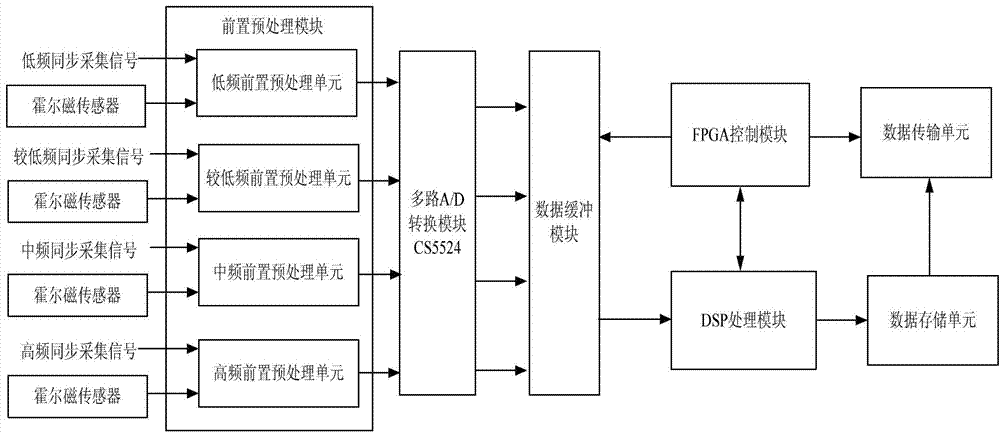
[0024] refer to figure 1 , a production well resistivity logging device, comprising a surface system 1, the surface system 1 is connected to the upper part of a centralizer 5 of a downhole logging device 3 through a cable 2, and the downhole logging device 3 includes a centralizer 5, an upper polarization power supply 6. The lower polarization power supply 7, the upper polarization device 10, the transmission control unit 12, the reception processing unit 13, the magnetic field detection unit 14, and the lower polarization device 17; the centralizer 5 is located at both ends of the downhole logging device 3 and Contact with the casing 4 ensures that the instrument is in the center position in the well; the upper polarization device 10 is in the center position in the wellbore, and the upper polarization frame 8 of the...


PUM


Abstract

A production well resistivity logging device comprises a ground system connected with an underground logging deivce through a cable. The underground logging deivce comprises a centralizer located at two ends of the logging device. An upper polarizing coil is wound on the outer portion of an upper polarizing framework of an upper polarizing device and is connected with the output end of the an upper polarizing power supply, the upper polarizing power supply is connected with an upper polarizing detection unit, an emission control unit is connected with a magnetic field detection unit, and a receiving processing unit is connected with the magnetic field detection unit. A lower polarizing device symmetrical to the upper polarizing device and having the same structure with the upper polarizing deivce is arranged on the tail portion of the underground logging deivce. The upper polarizing device and the lower polarizing device are totally same in structure and are only reverse in connected-in current polarities that one polarizing device performs polarizing and the other polarizing device performs demagnetizing. The production well resistivity logging device ensures that a sleeve is not damaged in the measurement process and self characteristics of the sleeve are not affected after measurement, can fast detect characteristics of the stratum outside the sleeve, and has the advantages of being efficient, fast, convenient and free of contact.

Description

technical field [0001] The invention belongs to the technical field of oil and gas resources and environment development, and in particular relates to a production well resistivity logging device for exploring the formation characteristics outside the casing of an oil field production well. Background technique [0002] With the deepening of oil and gas extraction, a large number of production wells have entered the middle and late stages of development one after another. Determining the distribution characteristics of remaining oil and evaluating the oil and gas depletion index have become the focus of attention in oil and gas field development. Through-casing resistivity logging mainly measures the change of formation resistivity outside the casing of the production well. It is useful for monitoring the dynamic distribution of reservoirs, studying oil layer productivity succession, well area water flooding effect, water flooding status, improving oilfield productivity, and ...

Claims


Application Information

Patent Timeline
Patent Type & Authority Applications(China)
IPC IPC(8): E21B49/00
Inventor 任志平党瑞荣党峰
Owner XI'AN PETROLEUM UNIVERSITY
Learn More